 ChipApex | Global Electronic Components Supplier
SEARCH
Search Product
Search Post
— IC芯片 | 连接器 | 传感器 | 被动器件 —
Search productSearch post
— IC芯片 | 连接器 | 传感器 | 被动器件 —
Consult the customer manager about the wholesale price.
consultation hotline:86-132-6715-2157
email:[email protected]
Contact the product manager for consultation. One-stop consultation is available.
Do you want a lower wholesale price? Please send us your inquiry and we will reply immediately.
The DMC4050SSD-13 is a complementary pair enhancement mode MOSFET manufactured by Diodes Incorporated. It integrates one N-channel and one P-channel device in an SO-8 surface-mount package. The N-channel Q1 supports a drain-source voltage of 40V with a maximum continuous drain current of 5.8A at 25°C, while the P-channel Q2 supports -40V and -5.8A. Both channels feature a maximum on-resistance of 45mΩ at VGS=10V and ID=3A. The device operates within a junction temperature range of -55°C to +150°C.
Verify component authenticity through authorized distribution channels. Confirm that the specific order matches the required datasheet revision DS33310 Rev. 4-2. Ensure compliance with RoHS directives and confirm suitability for intended operating temperatures before integration into final assemblies.
Select this component when matched N/P channel resistance is critical for minimizing conduction losses in dual-arm topologies. Evaluate thermal derating curves against expected ambient conditions. Verify gate drive voltage levels align with threshold specifications for optimal on-state performance.
This part belongs to the DMC4050 series of complementary MOSFETs from Diodes Incorporated. It serves as a standard discrete solution for applications requiring paired N and P channel devices in a compact footprint without automotive qualification suffixes.
For automotive applications requiring AEC-Q101 qualification and PPAP capability, consider the DMC4055SSDQ. Verify pinout compatibility and electrical parameter matching before substituting other generic complementary pairs.
The maximum continuous drain current for the N-channel Q1 is 5.8A at TA = +25°C.
No, this specific part number is not automotive qualified. Automotive-compliant versions are available under separate datasheets with Q-suffixes.
The device has a power dissipation rating of 1.25W to 2.14W depending on PCB copper coverage and measurement conditions, with a thermal resistance (junction-to-ambient) ranging from 58°C/W to 100°C/W.
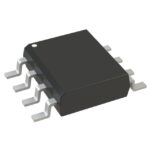 DMC4050SSD-13
The activity of extra discounts on wholesale prices is in full swing…
Please fill in your contact information and we will send you the latest wholesale price list.





