ChipApex | Global Electronic Components Supplier

SEARCH
Search Product
Search Post
— IC芯片 | 连接器 | 传感器 | 被动器件 —
Search productSearch post
— IC芯片 | 连接器 | 传感器 | 被动器件 —
Consult the customer manager about the wholesale price.
consultation hotline:86-132-6715-2157
email:[email protected]
Contact the product manager for consultation. One-stop consultation is available.
Do you want a lower wholesale price? Please send us your inquiry and we will reply immediately.
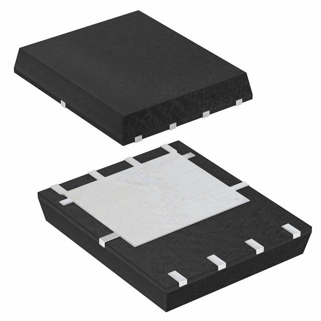
The DMP2003UPS-13 is a P-channel enhancement mode MOSFET from Diodes Incorporated, housed in an 8-pin PowerDI5060 surface-mount package. It features a drain-source voltage (VDS) of -20V and a continuous drain current (ID) of -150A at +25°C case temperature. The device exhibits a maximum on-resistance (RDS(ON)) of 2.2mΩ at VGS=-10V/-25A, 2.55mΩ at VGS=-4.5V/-20A, and 4.0mΩ at VGS=-2.5V/-15A. Total gate charge (Qg) is 177nC at VGS=-10V. Operating temperatures range from -55°C to +150°C.
Verify the specific ordering suffix '-13' corresponds to the standard tape and reel packaging configuration containing 2,500 units per carrier. Confirm that the component meets RoHS directives and is free of halogens and antimony if environmental compliance is required for the target assembly. Ensure the procurement documentation matches the manufacturer's official datasheet specifications.
Select this component when high current handling up to 150A is required within a low-profile footprint. Evaluate thermal resistance parameters based on the specific PCB copper area and mounting conditions, as dissipation capabilities vary significantly between ambient and case-referenced scenarios. Verify gate drive voltages align with the specified thresholds for optimal conduction performance.
This part belongs to the DMP series of P-channel MOSFETs manufactured by Diodes Incorporated. It utilizes the PowerDI5060-8 package, which provides a compact solution for high-current applications. The device represents a newer generation designed to balance low on-resistance with superior switching performance compared to previous iterations.
Consult Diodes Incorporated or authorized distributors for confirmed substitute part numbers. Do not assume functional equivalence with other generic P-channel MOSFETs without verifying pinout compatibility, voltage ratings, and thermal characteristics against the original datasheet.
The device supports a pulsed drain current of -350A with a 10μs pulse duration and 1% duty cycle.
The on-resistance increases as the junction temperature rises, as illustrated in the typical on-resistance versus junction temperature graphs provided in the datasheet.
 DMP2003UPS-13

The activity of extra discounts on wholesale prices is in full swing…
Please fill in your contact information and we will send you the latest wholesale price list.