 ChipApex | Global Electronic Components Supplier
SEARCH
Search Product
Search Post
— IC芯片 | 连接器 | 传感器 | 被动器件 —
Search productSearch post
— IC芯片 | 连接器 | 传感器 | 被动器件 —
Consult the customer manager about the wholesale price.
consultation hotline:86-132-6715-2157
email:[email protected]
Contact the product manager for consultation. One-stop consultation is available.
Do you want a lower wholesale price? Please send us your inquiry and we will reply immediately.
The DMP3068L-7 is a single P-channel enhancement mode MOSFET manufactured by Diodes Incorporated. It utilizes silicon technology and is housed in a standard SOT-23 surface-mount package. The device features a drain-source breakdown voltage of -30 V and a maximum continuous drain current of -3.9 A at +25°C. Its static drain-source on-resistance is specified as 72 mΩ at a gate-source voltage of -10 V, and 85 mΩ at -4.5 V. The total gate charge is 15.9 nC at -10 V. Operating temperatures range from -55°C to +150°C.
Verify the specific ordering suffix matches the required packaging quantity, such as the -7 suffix indicating a 3,000-unit tape and reel configuration. Confirm that the component meets all applicable environmental compliance standards relevant to the target market. Ensure the selected part number aligns with the intended thermal and electrical operating conditions defined in the official datasheet specifications.
Select this component based on its -30 V rating and 72 mΩ on-resistance characteristics suitable for low-voltage DC loads. Consider the SOT-23 package constraints regarding thermal dissipation capabilities when designing the PCB layout. Evaluate the gate threshold voltage requirements against the available control logic levels to ensure reliable turn-on and turn-off transitions under expected operating conditions.
This component belongs to the DMP3068 series of P-channel MOSFETs produced by Diodes Incorporated. The series focuses on optimizing the balance between conduction losses and switching speeds. The -7 suffix specifically denotes the standard tape and reel packaging format used for automated assembly processes in manufacturing environments.
Consult the manufacturer's official documentation for verified substitute part numbers within the same product family or equivalent specifications. Cross-reference pin configurations and thermal resistance values to ensure mechanical and electrical compatibility during replacement scenarios.
The maximum pulsed drain current is -18 A, provided the pulse width does not exceed 10 µs and the duty cycle remains at or below 1%.
The on-resistance increases as the junction temperature rises. Graphical data in the datasheet illustrates this positive temperature coefficient behavior across the operating range.
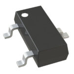 DMP3068L-7
The activity of extra discounts on wholesale prices is in full swing…
Please fill in your contact information and we will send you the latest wholesale price list.





