 ChipApex | Global Electronic Components Supplier
SEARCH
Search Product
Search Post
— IC芯片 | 连接器 | 传感器 | 被动器件 —
Search productSearch post
— IC芯片 | 连接器 | 传感器 | 被动器件 —
Consult the customer manager about the wholesale price.
consultation hotline:86-132-6715-2157
email:[email protected]
Contact the product manager for consultation. One-stop consultation is available.
Do you want a lower wholesale price? Please send us your inquiry and we will reply immediately.
The DMP45H21DHE-13 is a 450V P-channel enhancement mode MOSFET manufactured by Diodes Incorporated. It features a maximum drain-source voltage (BVDSS) of -450V and a continuous drain current (ID) of -0.27A at +25°C. The static drain-source on-resistance (RDS(ON)) is typically 13Ω with a maximum of 21Ω at VGS = -10V. The device operates within a junction temperature range of -55°C to +150°C, has a total power dissipation of 2.4W at +25°C, and utilizes an SOT223 package.
Verify the specific ordering suffix '-13' corresponds to the tape and reel packaging configuration containing 2,500 units per carrier. Confirm that the component meets RoHS 3 compliance standards and is halogen-free. Ensure the procurement channel is authorized to guarantee adherence to standard terms and conditions.
Select this component for high-voltage DC-DC converter designs requiring robust avalanche energy handling capabilities up to 30mJ. Evaluate the thermal resistance parameters against the specific PCB copper pad layout requirements. Consider the gate threshold voltage specifications when designing the control logic interface for reliable turn-on and turn-off states.
This part belongs to the DMP45H series of high-voltage P-channel MOSFETs from Diodes Incorporated. The series is engineered for telecom and general high-voltage switching environments. The device is housed in a lead-free SOT223 package with matte tin annealed terminals over a copper lead frame, ensuring compatibility with standard surface mount assembly processes.
Direct substitutes include other Diodes Incorporated parts within the DMP45H family, such as the DMP45H21DHE without the suffix or the DMP45H4D9HK3. Verify pinout compatibility and electrical ratings before substitution.
The DMP45H21DHE supports an avalanche energy (EAS) rating of 30 mJ under test conditions utilizing a 60mH inductor.
The typical on-resistance increases as the junction temperature rises from -55°C to +150°C, following the positive temperature coefficient characteristic shown in the transfer characteristics graphs.
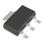 DMP45H21DHE-13
The activity of extra discounts on wholesale prices is in full swing…
Please fill in your contact information and we will send you the latest wholesale price list.





