 ChipApex | Global Electronic Components Supplier
SEARCH
Search Product
Search Post
— IC芯片 | 连接器 | 传感器 | 被动器件 —
Search productSearch post
— IC芯片 | 连接器 | 传感器 | 被动器件 —
Consult the customer manager about the wholesale price.
consultation hotline:86-132-6715-2157
email:[email protected]
Contact the product manager for consultation. One-stop consultation is available.
Do you want a lower wholesale price? Please send us your inquiry and we will reply immediately.
The DMP56D0UFB-7B is a P-channel enhancement mode MOSFET manufactured by Diodes Incorporated. It features a maximum drain-source voltage (V(BR)DSS) of -50 V and a gate-source voltage (VGSS) rating of ±8 V. The device provides a continuous drain current (ID) of -200 mA at +25°C, with a pulsed drain current (IDM) capability of -700 mA. Static drain-source on-resistance (RDS(on)) is specified as 6 Ω at VGS = -4 V and ID = -100 mA, or 8 Ω at VGS = -2.5 V and ID = -80 mA. Total power dissipation (PD) is rated at 425 mW, supported by a thermal resistance (RθJA) of 275 °C/W. The component operates within a junction temperature range of -55 to +150 °C.
Verify the specific ordering suffix '-7B' against official manufacturer documentation to confirm the 10,000-unit tape and reel packing quantity. Ensure that the X1-DFN1006-3 package dimensions and terminal finish specifications align with your PCB layout requirements. Confirm RoHS compliance status and halogen-free definitions directly from the datasheet before finalizing procurement.
Select this component when a -50 V P-channel MOSFET with low RDS(on) is required for compact designs. The X1-DFN1006-3 package offers a small footprint suitable for space-constrained applications. Evaluate the 425 mW power dissipation limit and 275 °C/W thermal resistance to ensure adequate heat sinking or PCB copper area allocation for your specific operating conditions.
This part belongs to the DMP56D0UFB series of P-channel enhancement mode MOSFETs from Diodes Incorporated. It utilizes an X1-DFN1006-3 surface-mount package designed for efficient thermal performance in small form factors. The series is engineered to minimize on-state resistance while maintaining superior switching capabilities for modern electronic systems.
Consult official Diodes Incorporated documentation for confirmed substitute part numbers. Verify electrical parameters, pin configurations, and package dimensions match your design requirements before substitution.
The maximum pulsed drain current (IDM) is -700 mA, provided the pulse width is ≤10µS and the duty cycle is ≤1%.
The on-resistance increases as the junction temperature rises. Typical curves show higher resistance values at elevated temperatures like 125°C and 150°C compared to room temperature.
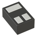 DMP56D0UFB-7B
The activity of extra discounts on wholesale prices is in full swing…
Please fill in your contact information and we will send you the latest wholesale price list.





