ChipApex | Global Electronic Components Supplier
SEARCH
Search Product
Search Post
— IC芯片 | 连接器 | 传感器 | 被动器件 —
Search productSearch post
— IC芯片 | 连接器 | 传感器 | 被动器件 —
Consult the customer manager about the wholesale price.
consultation hotline:86-132-6715-2157
email:[email protected]
Contact the product manager for consultation. One-stop consultation is available.
Do you want a lower wholesale price? Please send us your inquiry and we will reply immediately.
The FGH60N60SMD is a Field Stop IGBT manufactured by onsemi, designed for applications requiring low conduction and switching losses. It features a collector-emitter breakdown voltage (VCES) of 600 V and a continuous collector current (IC) of 120 A at 25°C case temperature. The device operates with a maximum junction temperature (TJ) of 175°C and offers a typical saturation voltage (VCE(sat)) of 1.9 V at IC = 60 A. Key dynamic parameters include a total gate charge (Qg) of 189 nC, turn-on delay time (Td(on)) of 18 ns, and turn-off delay time (Td(off)) of 104 ns under standard test conditions. The component is housed in a TO-247-3LD package.
Verify the specific ordering suffix and packaging configuration when sourcing this component. Confirm that the received parts match the manufacturer's marking diagram and date code requirements. Ensure compliance with environmental regulations such as RoHS and REACH during procurement. Check for any recent product change notices regarding assembly plant or material declarations before placing orders.
Select this component based on its 600 V blocking capability and 120 A current rating suitable for medium-power industrial applications. Consider the thermal resistance values and maximum junction temperature limits for heat sink design. Evaluate the switching energy losses against the required operating frequency and gate drive resistance to ensure efficiency targets are met within the safe operating area.
This part belongs to onsemi’s second-generation Field Stop IGBT series. It shares the TO-247-3LD mechanical outline with other devices in the family but differs in electrical ratings and switching characteristics. The FGH60N60SMD is distinct from MOSFET alternatives due to its bipolar conduction mechanism and specific gate charge profile.
Direct replacements must maintain the 600 V / 60 A rating and TO-247-3LD package. Verify pinout compatibility and thermal interface dimensions. Compare switching speeds and saturation voltages to ensure equivalent circuit performance without exceeding gate drive limitations.
The absolute maximum transient gate-to-emitter voltage is ±30 V, while the continuous rating is ±20 V.
The device exhibits a positive temperature coefficient; VCE(sat) increases as the junction temperature rises, reaching a typical value of 2.1 V at TC = 175°C compared to 1.9 V at 25°C.
The diode reverse recovery time (Trr) is typically 30 ns at TC = 25°C and increases to 72 ns at TC = 175°C.
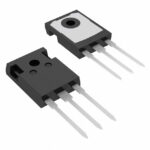 FGH60N60SMD
The activity of extra discounts on wholesale prices is in full swing…
Please fill in your contact information and we will send you the latest wholesale price list.