ChipApex | Global Electronic Components Supplier
SEARCH
Search Product
Search Post
— IC芯片 | 连接器 | 传感器 | 被动器件 —
Search productSearch post
— IC芯片 | 连接器 | 传感器 | 被动器件 —
Consult the customer manager about the wholesale price.
consultation hotline:86-132-6715-2157
email:[email protected]
Contact the product manager for consultation. One-stop consultation is available.
Do you want a lower wholesale price? Please send us your inquiry and we will reply immediately.
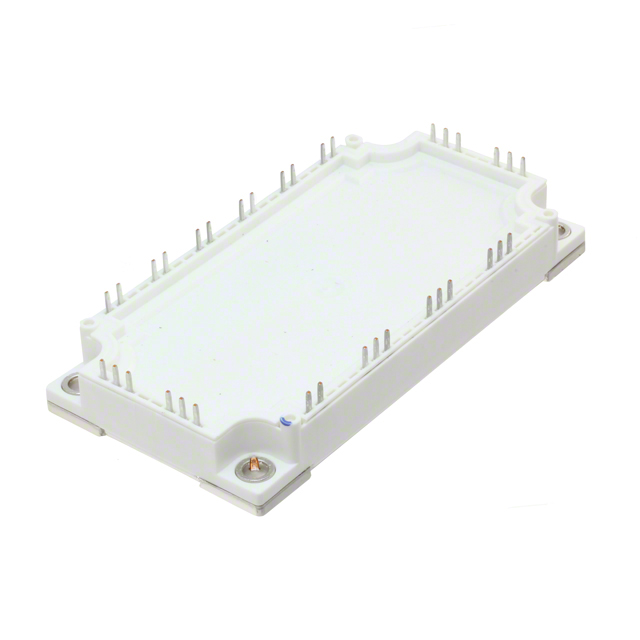
The FS150R17PE4BOSA1 is an EconoPACK™4 module featuring Trench/Fieldstop IGBT4 and Emitter Controlled 4 diode technology. It provides a collector-emitter voltage (VCES) of 1700 V, with a continuous DC collector current (IC nom) of 150 A at TC = 100°C and a repetitive peak collector current (ICRM) of 300 A. The module includes an integrated NTC thermistor with a rated resistance of 5.0 kΩ at 25°C. Key electrical parameters include a typical VCEsat of 2.30 V at Tvj = 125°C and a gate threshold voltage (VGEth) ranging from 5.20 V to 6.40 V. Thermal resistance from junction to case is 0.180 K/W for the IGBT and 0.340 K/W for the diode.
Verify the specific ordering suffix BOSA1 against official Infineon documentation to confirm package type and terminal configuration. Ensure compatibility with existing PCB layouts and cooling systems. Confirm that the PressFIT termination method aligns with assembly equipment capabilities. Validate thermal interface material specifications for the required thermal resistance values.
Select this component for applications requiring 1700 V blocking capability and 150 A continuous current handling. Consider the positive temperature coefficient of VCEsat for parallel operation stability. Evaluate the stray inductance of 20 nH for circuit layout optimization. Ensure the drive circuit supports the specified gate voltage range of +/-20 V and internal gate resistor of 5.0 Ω.
This part belongs to the Infineon EconoPACK™4 family, designed for compact high-power modules. It integrates advanced IGBT4 and EC4 diode technologies within a standardized housing. The series emphasizes high power density and reliable thermal management through its isolated base plate construction.
Consult official Infineon cross-reference guides for verified substitutes. Ensure any replacement matches the 1700 V rating, 150 A current capacity, and EconoPACK™4 mechanical footprint. Verify equivalent thermal resistance and switching characteristics before implementation.
The module can withstand a short-circuit condition for a maximum duration of 10 µs when the junction temperature is 150°C and the collector current is limited to 700 A.
The isolation test voltage is 3.4 kV RMS at 50 Hz for a duration of 1 minute.
The VCEsat exhibits a positive temperature coefficient, increasing from a typical 1.95 V at 25°C to 2.45 V at 150°C under rated conditions.
 FS150R17PE4BOSA1
The activity of extra discounts on wholesale prices is in full swing…
Please fill in your contact information and we will send you the latest wholesale price list.