ChipApex | Global Electronic Components Supplier

SEARCH
Search Product
Search Post
— IC芯片 | 连接器 | 传感器 | 被动器件 —
Search productSearch post
— IC芯片 | 连接器 | 传感器 | 被动器件 —
Consult the customer manager about the wholesale price.
consultation hotline:86-132-6715-2157
email:[email protected]
Contact the product manager for consultation. One-stop consultation is available.
Do you want a lower wholesale price? Please send us your inquiry and we will reply immediately.
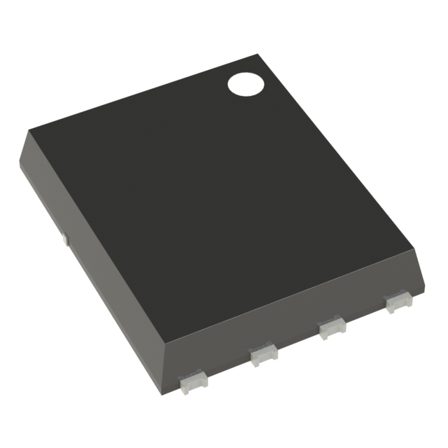
IPG15N06S3L-45 is listed in the FET, MOSFET Arrays range at ChipApex. The manufacturer field lists Infineon Technologies. Its product description is MOSFET 2N-CH 55V 15A 8TDSON. Review the specifications below when checking this part for your BOM.
The IPG15N06S3L-45 is an OptiMOS-T dual N-channel logic level enhancement mode power transistor in a PG-TDSON-8-4 package. It features a drain-source voltage of 55 V and a continuous drain current of 15 A per channel at 25 °C. The maximum on-state resistance is 45 mΩ at VGS=10 V and 80 mΩ at VGS=5 V. Total gate charge is 20 nC, with a threshold voltage range of 1.2 V to 2.2 V. Power dissipation is 21 W at 25 °C, operating temperature ranges from -55 °C to +175 °C, and it is AEC-Q101 qualified.
Verify the specific ordering suffix against official Infineon documentation to confirm exact packaging and reel specifications. Confirm RoHS compliance status and lead times directly with authorized distributors or the manufacturer before finalizing procurement plans.
Select this component for designs requiring dual isolated channels in a small footprint. Ensure the driving circuit can supply sufficient gate voltage to achieve the lower 45 mΩ resistance threshold. Verify that the PCB copper area meets the thermal requirements for the specified power dissipation limits.
This device belongs to the OptiMOS-T family of power transistors manufactured by Infineon Technologies. It utilizes silicon technology optimized for low on-resistance and fast switching speeds. The component is designed for high-volume manufacturing and general-purpose power switching applications.
Consult official Infineon replacement guides for verified substitutes. Cross-reference pinouts and electrical parameters carefully when considering alternative manufacturers' components.
The single pulse avalanche energy (EAS) is rated at 47 mJ when the avalanche current is 7.5 A.
Yes, the IPG15N06S3L-45 is qualified according to the AEC-Q101 standard.
The typical reverse recovery charge (Qrr) is 9 nC under test conditions of VR=27.5 V and diF/dt=100 A/µs.
Explore related parts through FETs, MOSFETs, Transistors, Discrete Semiconductor Products, all product categories.
 IPG15N06S3L-45

The activity of extra discounts on wholesale prices is in full swing…
Please fill in your contact information and we will send you the latest wholesale price list.