ChipApex | Global Electronic Components Supplier

SEARCH
Search Product
Search Post
— IC芯片 | 连接器 | 传感器 | 被动器件 —
Search productSearch post
— IC芯片 | 连接器 | 传感器 | 被动器件 —
Consult the customer manager about the wholesale price.
consultation hotline:86-132-6715-2157
email:[email protected]
Contact the product manager for consultation. One-stop consultation is available.
Do you want a lower wholesale price? Please send us your inquiry and we will reply immediately.
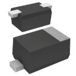
MA2SP0500L is listed in the RF Diode range at ChipApex. The manufacturer field lists Panasonic Electronic Components. Its product description is RF DIODE PIN 60V SSMINI2-F1. Review the specifications below when checking this part for your BOM.
The MA2SP05 is a silicon epitaxial planar PIN diode designed for high-frequency attenuator applications. It features a miniature SC-79 SSMini2-F1 surface-mount package. Key electrical parameters include a maximum reverse voltage of 60 V and a forward current rating of 50 mA at 25°C. The device exhibits a typical terminal capacitance of 2.4 pF at 0 V reverse bias and 1 MHz, with a forward dynamic resistance of 5.5 Ω at 10 mA forward current and 100 MHz. Forward voltage is typically 1.0 V at 10 mA, while reverse current remains below 100 nA at 60 V.
Verify the current lifecycle status on the manufacturer's website before procurement, as this component may be in a maintenance or discontinued phase. Confirm that the specific order quantity meets any minimum packaging requirements defined by the distributor. Ensure the RoHS compliance declaration matches the project specifications. Request the latest product standards to confirm no recent specification changes have occurred prior to finalizing the purchase order.
Select this component when low terminal capacitance and controlled dynamic resistance are critical for high-frequency attenuation circuits. The SC-79 package suits designs requiring small footprint surface mounting. Verify that the operating environment stays within the specified junction temperature range of -55°C to +150°C. Ensure the circuit design does not exceed the absolute maximum ratings for reverse voltage or forward current under transient conditions.
This part belongs to Panasonic's PIN diode family, specifically engineered for RF switching and attenuation roles. The silicon epitaxial planar construction provides stable performance across varying frequencies. It serves as a discrete semiconductor solution for signal conditioning in standard commercial electronics, distinct from integrated RF modules.
Consult the manufacturer's official replacement list for direct equivalents. Verify pinout compatibility and package dimensions if substituting with other SC-79 devices. Ensure the alternative component meets the same 2.4 pF capacitance and 5.5 Ω dynamic resistance targets at 100 MHz.
The typical terminal capacitance is 2.4 pF, measured at 0 V reverse bias and 1 MHz frequency.
The forward dynamic resistance is typically 5.5 Ω when driven with 10 mA forward current at 100 MHz.
No. The datasheet specifies it is intended for standard applications like office and communications equipment. Special applications such as aerospace require consultation with sales staff due to higher reliability requirements.
Explore related parts through Diodes, Discrete Semiconductor Products, all product categories, ChipApex homepage.
 MA2SP0500L

The activity of extra discounts on wholesale prices is in full swing…
Please fill in your contact information and we will send you the latest wholesale price list.