ChipApex | Global Electronic Components Supplier

SEARCH
Search Product
Search Post
— IC芯片 | 连接器 | 传感器 | 被动器件 —
Search productSearch post
— IC芯片 | 连接器 | 传感器 | 被动器件 —
Consult the customer manager about the wholesale price.
consultation hotline:86-132-6715-2157
email:[email protected]
Contact the product manager for consultation. One-stop consultation is available.
Do you want a lower wholesale price? Please send us your inquiry and we will reply immediately.
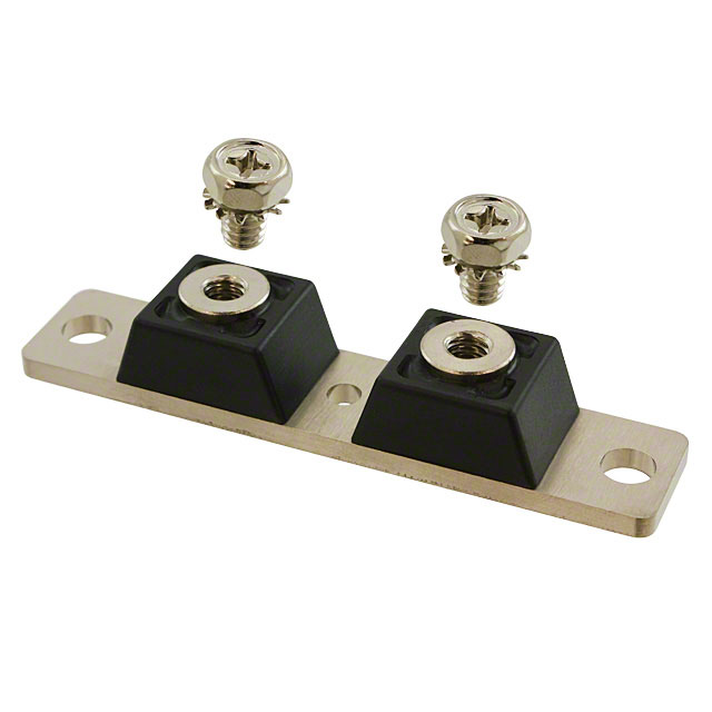
MBR40035CTRL is listed in the Diode Arrays range at ChipApex. The manufacturer field lists GeneSiC Semiconductor. Its product description is DIODE MOD SCHOTT 35V 200A 2TOWER. Review the specifications below when checking this part for your BOM.
The MBR40035CTRL is a Schottky rectifier module manufactured by GeneSiC Semiconductor. It features a maximum DC blocking voltage of 35 V and an average forward current rating of 400 A per package. The device supports a peak forward surge current of 3000 A per leg under specified conditions. Electrical characteristics include a maximum instantaneous forward voltage of 0.60 V and a maximum instantaneous reverse current of 250 mA at rated voltage. Thermal performance is defined by a maximum junction-to-case thermal resistance of 0.35 °C/W per leg.
Verify the specific ordering suffix against official documentation to confirm terminal configuration and packaging variations. Confirm RoHS compliance status and lead times directly with authorized distributors or the manufacturer, as availability may vary by region. Ensure thermal management solutions align with the specified junction-to-case thermal resistance requirements for reliable operation.
Select this component for applications requiring high current handling capabilities combined with low conduction losses. Evaluate the thermal resistance specifications against the system's cooling capacity to ensure junction temperatures remain within the operational range. Consider the physical dimensions and mounting requirements to ensure compatibility with the intended PCB or chassis design.
This part belongs to the MBR400 series of Schottky diode modules from GeneSiC Semiconductor. These modules are engineered for high-power density applications where efficiency and thermal performance are critical. The series typically utilizes silicon technology to provide reliable rectification in demanding industrial environments.
Consult official cross-reference guides for verified substitutes. Ensure any replacement matches the 35 V voltage rating, 400 A current capacity, and compatible mounting style. Verify that thermal resistance and package dimensions are equivalent to maintain system integrity.
The maximum thermal resistance from junction to case is 0.35 °C/W per leg.
The device can withstand a peak forward surge current of 3000 A per leg for an 8.3 ms half-sine pulse.
The storage and operating temperature range extends from -55 °C to +150 °C.
Explore related parts through Rectifiers, Diodes, Discrete Semiconductor Products, all product categories.
 MBR40035CTRL

The activity of extra discounts on wholesale prices is in full swing…
Please fill in your contact information and we will send you the latest wholesale price list.