 ChipApex | Global Electronic Components Supplier

SEARCH
Search Product
Search Post
— IC芯片 | 连接器 | 传感器 | 被动器件 —
Search productSearch post
— IC芯片 | 连接器 | 传感器 | 被动器件 —
Consult the customer manager about the wholesale price.
consultation hotline:86-132-6715-2157
email:[email protected]
Contact the product manager for consultation. One-stop consultation is available.
Do you want a lower wholesale price? Please send us your inquiry and we will reply immediately.
The PJX8601_R1_00001 is a complementary enhancement mode MOSFET featuring integrated ESD protection, housed in an SOT-563 package. It integrates one N-channel and one P-channel transistor within a single silicon component. The N-channel device supports a drain-source voltage of 20 V with a continuous current of 0.5 A, while the P-channel device handles -20 V and -0.5 A. Key electrical parameters include a maximum gate-source voltage of ±10 V, a power dissipation rating of 300 mW at 25°C, and a junction temperature range from -55°C to +150°C.
Verify the specific ordering suffix _R1_00001 against official Panjit documentation to confirm the standard reel packing configuration. Ensure that the required marking version X61 aligns with your manufacturing assembly specifications. Cross-reference the datasheet revision date to guarantee access to the most current thermal and electrical characteristic curves before finalizing procurement orders.
Select this component when space-constrained designs require both N-channel and P-channel switching capabilities in a single footprint. The low threshold voltage characteristics make it suitable for logic-level driving scenarios. Verify that the 300 mW power dissipation limit accommodates the expected thermal load under continuous operating conditions without exceeding the maximum junction temperature rating.
This part belongs to the NFET-20TENP series manufactured by Panjit International Inc. It utilizes the SOT-563 surface-mount package, which provides a compact form factor for dual-transistor integration. The product line focuses on providing complementary MOSFET solutions optimized for portable electronics and low-power switching applications requiring robust ESD performance.
Publicly confirmed substitute part numbers are not available in the provided documentation. Verify pinout compatibility and absolute maximum ratings if considering alternative manufacturers' complementary MOSFETs in the SOT-563 package.
The typical total gate charge (Qg) for the N-channel device is 1.4 nC, measured at VDS=10V, ID=500mA, and VGS=4.5V.
For the N-channel device, RDS(on) decreases as VGS increases, ranging from a maximum of 3.0 Ω at VGS=1.2V to 0.4 Ω at VGS=4.5V.
The typical turn-off fall time (tf) for the P-channel device is 116 ns, measured under specific test conditions including VDD=-10V and RG=6Ω.
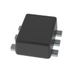 PJX8601_R1_00001

The activity of extra discounts on wholesale prices is in full swing…
Please fill in your contact information and we will send you the latest wholesale price list.





