 ChipApex | Global Electronic Components Supplier
SEARCH
Search Product
Search Post
— IC芯片 | 连接器 | 传感器 | 被动器件 —
Search productSearch post
— IC芯片 | 连接器 | 传感器 | 被动器件 —
Consult the customer manager about the wholesale price.
consultation hotline:86-132-6715-2157
email:[email protected]
Contact the product manager for consultation. One-stop consultation is available.
Do you want a lower wholesale price? Please send us your inquiry and we will reply immediately.
The InterFET SMP5484TR is an N-channel Junction Field-Effect Transistor (JFET) utilizing the InterFET N0026S geometry. It is housed in a surface-mount SOT23 package and supplied on a 7-inch or 13-inch tape and reel with minimum quantities of 1,000 pieces. The device is engineered for low noise and low leakage performance, featuring a typical input capacitance of 4.3pF and gate leakage below 10pA at room temperature. Key electrical parameters include a Gate-to-Source Breakdown Voltage of -25V, a Drain-to-Source Saturation Current range of 1mA to 5mA, and a Gate-to-Source Cutoff Voltage between -0.3V and -3V.
Verify that the specific ordering suffix TR corresponds to the tape and reel packaging format required for automated assembly processes. Confirm the minimum order quantity aligns with the manufacturer's standard reel sizes. Ensure the component meets RoHS compliance standards if mandated by the end application regulations. Validate that the SOT23 footprint matches the intended PCB layout design.
Select this component when designing circuits requiring high-frequency operation with minimal noise interference. The low input capacitance makes it suitable for applications where signal integrity is critical at VHF and UHF frequencies. Consider the specific IDSS and VGS(off) ranges to ensure biasing compatibility within the target circuit topology.
This part belongs to the 2N5484-5-6 family of N-channel JFETs manufactured by InterFET. While the base 2N5484 is available in through-hole TO-92 packages, the SMP5484 variant specifically denotes the surface-mount SOT23 configuration. The TR suffix indicates the reel-based packaging method used for high-volume manufacturing integration.
Direct substitutes within the same family include the SMP5485TR and SMP5486TR. These alternatives share identical packaging and general characteristics but differ in saturation current and cutoff voltage specifications. Verify electrical parameter compatibility before substitution.
The absolute maximum rating for continuous forward gate current is -25 mA.
Yes, the suggested land pattern data indicates that a more robust pattern may be desired for wave soldering applications.
The device supports an operating junction temperature range from -55°C to 125°C.
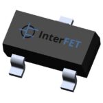 SMP5484TR
The activity of extra discounts on wholesale prices is in full swing…
Please fill in your contact information and we will send you the latest wholesale price list.





