 ChipApex | Global Electronic Components Supplier
SEARCH
Search Product
Search Post
— IC芯片 | 连接器 | 传感器 | 被动器件 —
Search productSearch post
— IC芯片 | 连接器 | 传感器 | 被动器件 —
Consult the customer manager about the wholesale price.
consultation hotline:86-132-6715-2157
email:[email protected]
Contact the product manager for consultation. One-stop consultation is available.
Do you want a lower wholesale price? Please send us your inquiry and we will reply immediately.
The B11G1822N60DYZ is a dual-section, fully integrated Doherty Monolithic Microwave Integrated Circuit (MMIC) utilizing LDMOS technology. It operates within the 1800 MHz to 2200 MHz frequency range and integrates carrier and peaking devices, input splitters, output combiners, and pre-matches. The device features independent bias control for carrier and peaking sections, an integrated bias gate switch, and ESD protection. Key electrical parameters include a drain-source voltage of 65 V, gate-source voltage limits from -0.5 V to +13 V, and a maximum junction temperature of 200 °C. At 2000 MHz with 5 W output power, it delivers a typical power gain of 29 dB and drain efficiency of 29%.
Verify the specific ordering suffix 'YZ' corresponds to the 300-piece reel packaging configuration as defined in Ampleon's official documentation. Confirm RoHS compliance status through the manufacturer's product details page prior to procurement. Ensure handling procedures adhere to CDM Class C2A and HBM Class 1C electrostatic discharge sensitivity ratings during assembly.
Select this component for applications requiring high linearity and large instantaneous bandwidth in the 1800–2200 MHz band. The integrated Doherty topology simplifies design by eliminating external matching networks for the combiner and splitter. Verify that the application circuit can support the required 5 V logic level for the PA enable signal and provides adequate thermal management for the PQFN package.
This part belongs to Ampleon's portfolio of LDMOS-based RF power amplifiers designed for telecommunications infrastructure. The B11G1822N60D series specifically targets multi-band driver applications where high efficiency and linearity are critical. It represents a consolidated solution replacing discrete amplifier stages with a single MMIC component.
The datasheet lists B11G1822N60DX as an alternative orderable part number with identical electrical specifications but differing in packing quantity (1500 pieces vs. 300 pieces). No other functional substitutes are documented in the provided source material.
The B11G1822N60D can withstand a load mismatch corresponding to VSWR = 10:1 through all phases under specified operating conditions.
The PA enable trigger signal (PA_e) controls the IDq-bias ON/OFF state. A logic HIGH (5 V) turns the bias on, while a logic LOW (0 V) turns it off.
An RC circuit must be implemented at the gate bias to ensure improved linearity and stability. This implementation must be symmetrical between both amplifier sections.
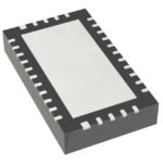 B11G1822N60DYZ
The activity of extra discounts on wholesale prices is in full swing…
Please fill in your contact information and we will send you the latest wholesale price list.





