ChipApex | Global Electronic Components Supplier
SEARCH
Search Product
Search Post
— IC芯片 | 连接器 | 传感器 | 被动器件 —
Search productSearch post
— IC芯片 | 连接器 | 传感器 | 被动器件 —
Consult the customer manager about the wholesale price.
consultation hotline:86-132-6715-2157
email:[email protected]
Contact the product manager for consultation. One-stop consultation is available.
Do you want a lower wholesale price? Please send us your inquiry and we will reply immediately.
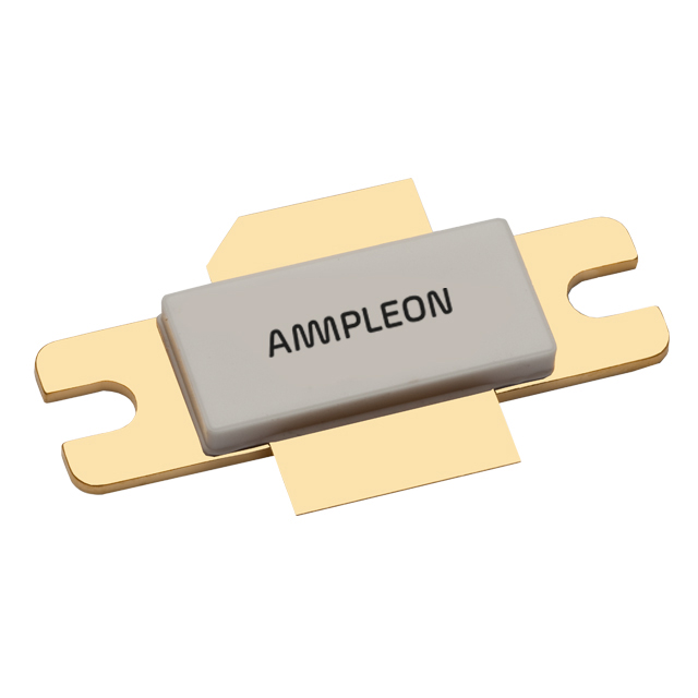
The BLF7G24L-140 is a 140 W LDMOS power transistor designed for base station applications operating between 2300 MHz and 2400 MHz. It supports single carrier IS-95 with a peak-to-average ratio of 9.7 dB at 0.01% probability on the CCDF, utilizing Walsh codes 8 through 13 and a channel bandwidth of 1.2288 MHz. For 3GPP test model 1 with 64 DPCH, it handles a peak-to-average ratio of 7.2 dB at 0.01% probability with a 3.84 MHz channel bandwidth. The device operates with a drain-source voltage of 28 V and a quiescent current of 1300 mA.
Verify the specific package variant required for the design, as the BLF7G24L-140 corresponds to the SOT502A flanged ceramic package with mounting holes, while the BLF7G24LS-140 uses the SOT502B earless flanged package. Confirm RoHS compliance status and ensure the ordering suffix matches the exact physical lead configuration needed for the PCB layout.
Select this component for high-power RF amplification in cellular infrastructure within the specified frequency band. Ensure the thermal management system can handle the junction-to-case thermal resistance of 0.28 K/W at 125 W dissipation. Verify that the input return loss meets the system requirements, as typical values are around -12 dB.
This part belongs to the Ampleon 7G series of LDMOS transistors, specifically engineered for wireless communication infrastructure. The BLF7G24L-140 is distinct from the BLF7G22L due to its higher power output and specific frequency targeting. It represents a mature production specification released in September 2015, superseding earlier preliminary versions.
The BLF7G24LS-140 serves as a direct mechanical alternative if an earless flanged package (SOT502B) is preferred over the standard flanged version (SOT502A). Both variants share identical electrical characteristics. No other cross-compatible substitutes are documented in the official datasheet.
 BLF7G24L-140,112
The activity of extra discounts on wholesale prices is in full swing…
Please fill in your contact information and we will send you the latest wholesale price list.