ChipApex | Global Electronic Components Supplier
SEARCH
Search Product
Search Post
— IC芯片 | 连接器 | 传感器 | 被动器件 —
Search productSearch post
— IC芯片 | 连接器 | 传感器 | 被动器件 —
Consult the customer manager about the wholesale price.
consultation hotline:86-132-6715-2157
email:[email protected]
Contact the product manager for consultation. One-stop consultation is available.
Do you want a lower wholesale price? Please send us your inquiry and we will reply immediately.
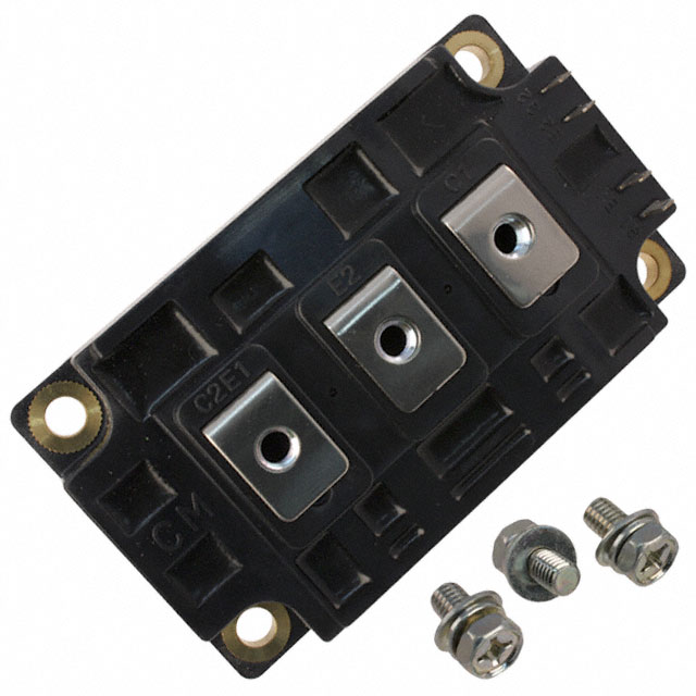
The CM400DY-12H is a Dual IGBTMOD™ H-Series power module manufactured by Powerex, Inc. It features a half-bridge configuration with two IGBT transistors and reverse-connected super-fast recovery free-wheel diodes. The device supports a collector-emitter voltage (V_CES) of 600 Volts and a continuous collector current (I_C) of 400 Amperes. Key electrical parameters include a maximum junction temperature of 150 °C, a typical saturation voltage (V_CE(sat)) of 2.1 Volts at 400A, and a gate threshold voltage ranging from 4.5 to 7.5 Volts. The module provides an isolation voltage of 2500 Vrms and operates within a storage temperature range of -40 to 125 °C.
Verify the specific manufacturer origin, as this model was originally developed by Mitsubishi Electric before Powerex acquired the relevant assets. Confirm RoHS compliance status and check for any updated datasheet revisions or ordering suffixes that may indicate packaging or material changes. Ensure the supplier provides valid traceability documentation for critical industrial deployments.
Select this module for applications requiring a 600V rating and up to 400A continuous current in a compact half-bridge format. Evaluate the thermal resistance values against your heatsink capabilities to ensure the junction temperature remains within the 150 °C limit under peak load conditions. Consider the 70ns diode recovery time when designing snubber circuits or assessing switching losses at frequencies up to 25kHz.
This component belongs to the IGBTMOD™ H-Series line, which represents standard silicon IGBT technology designed for general-purpose high-power switching. The 'DY' designation indicates a dual unit configuration, while '12' specifies the 600V voltage class. This series is engineered to balance performance and cost for medium-to-high power industrial electronics.
Direct replacements must match the 600V/400A rating and half-bridge pinout. Verify mechanical dimensions, specifically the M6 mounting threads and terminal spacing, to ensure compatibility with existing PCB layouts and heatsinks without redesigning the mechanical interface.
The absolute maximum rating for the Gate-Emitter Voltage (V_GES) is ±20 Volts. Exceeding this limit risks damaging the gate oxide layer.
The Collector-Emitter Saturation Voltage (V_CE(sat)) increases with temperature. At 25 °C, it is typically 2.1 Volts, rising to approximately 2.15 Volts at 150 °C under rated current conditions.
The Diode Reverse Recovery Time (t_rr) is specified as a maximum of 110 ns when tested at 400A with a di/dt of -800A/μs.
 CM400DY-12H
The activity of extra discounts on wholesale prices is in full swing…
Please fill in your contact information and we will send you the latest wholesale price list.