ChipApex | Global Electronic Components Supplier
SEARCH
Search Product
Search Post
— IC芯片 | 连接器 | 传感器 | 被动器件 —
Search productSearch post
— IC芯片 | 连接器 | 传感器 | 被动器件 —
Consult the customer manager about the wholesale price.
consultation hotline:86-132-6715-2157
email:[email protected]
Contact the product manager for consultation. One-stop consultation is available.
Do you want a lower wholesale price? Please send us your inquiry and we will reply immediately.
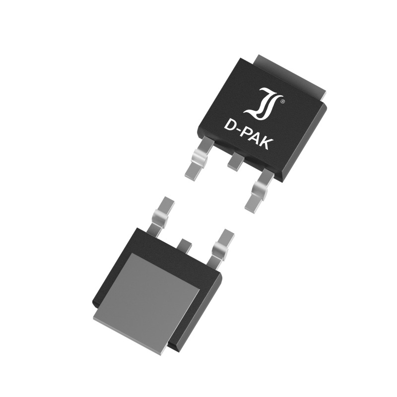
The DI1A5N60D1 is an N-Channel Power MOSFET manufactured by Diotec Semiconductor, housed in a TO-252AA (D-PACK) package. It features a drain-source voltage of 600 V and a continuous drain current of 1.5 A at 25°C case temperature. The device exhibits a maximum on-state resistance of 8 Ω at VGS = 10 V. Key electrical parameters include a gate-source threshold voltage ranging from 2 V to 4 V, a total gate charge of 7.9 nC, and a power dissipation capacity of 25 W at 25°C. The component supports a single pulse avalanche energy of 30 mJ and operates within a junction temperature range of -55°C to +150°C.
Verify the specific ordering suffix when purchasing. The standard version is commercial/industrial grade. Suffix -Q indicates AEC-Q101 compliance, while -AQ denotes qualification status. Confirm these designations match project requirements before procurement. Ensure the datasheet version matches the manufacturing batch specifications.
Select this component for circuits requiring 600 V blocking capability with moderate current handling up to 1.5 A. The 8 Ω maximum RDS(on) impacts conduction losses; verify thermal management strategies accordingly. Consider the 7.9 nC gate charge for driver selection. The TO-252AA package requires appropriate PCB copper pad sizing for optimal heat dissipation.
This part belongs to Diotec's discrete semiconductor portfolio, specifically the N-Channel Power MOSFET category. It utilizes advanced trench technology to achieve performance metrics suitable for general-purpose power switching. The product line includes variants with different automotive qualifications indicated by suffixes.
Public confirmed substitute part numbers are not available in the provided documentation. Verify pinout compatibility and electrical parameter margins if considering alternative manufacturers.
The DI1A5N60D1 supports a single pulse avalanche energy of 30 mJ under specified test conditions.
The suffix -Q indicates AEC-Q101 compliance, while -AQ indicates the component is in AEC-Q101 qualification. Standard versions are commercial/industrial grade.
The typical turn-on delay time is 2.7 ns, measured at VDD = 300 V, ID = 1.5 A, and RG = 10 Ω.
 DI1A5N60D1
The activity of extra discounts on wholesale prices is in full swing…
Please fill in your contact information and we will send you the latest wholesale price list.