 ChipApex | Global Electronic Components Supplier

SEARCH
Search Product
Search Post
— IC芯片 | 连接器 | 传感器 | 被动器件 —
Search productSearch post
— IC芯片 | 连接器 | 传感器 | 被动器件 —
Consult the customer manager about the wholesale price.
consultation hotline:86-132-6715-2157
email:[email protected]
Contact the product manager for consultation. One-stop consultation is available.
Do you want a lower wholesale price? Please send us your inquiry and we will reply immediately.
The DMN4026SSD-13 is a dual N-channel enhancement mode MOSFET manufactured by Diodes Incorporated. It features a maximum drain-source voltage (V_DSS) of 40 V and a gate-source voltage (V_GSS) of ±20 V. The device provides a continuous drain current (I_D) of 7.0 A at +25°C, with a peak pulsed current of 70 A. The static drain-source on-resistance (R_DS(ON)) is specified as 24 mΩ max at V_GS = 10 V and 32 mΩ max at V_GS = 4.5 V. Total gate charge (Q_g) reaches 19.1 nC typ at V_GS = 10 V. Thermal resistance from junction to ambient is 98 °C/W steady state. The component operates within a temperature range of -55°C to +150°C.
Verify the specific ordering suffix '-13' corresponds to the 2,500-unit reel packaging format when sourcing components. Confirm that the requested units match the manufacturer's standard packing quantity requirements. Ensure compliance with environmental directives such as RoHS 3 and halogen-free specifications during procurement validation.
Select this component for applications requiring a 40 V rating with high efficiency. Evaluate the R_DS(ON) values against the system's gate drive voltage to ensure adequate current handling. Consider the thermal resistance parameters for heat dissipation planning in enclosed environments.
This part belongs to the DMN40 series of dual N-channel MOSFETs from Diodes Incorporated. These devices are engineered to balance low on-resistance with superior switching performance. The series targets high-efficiency power management solutions across various industrial and consumer electronics sectors.
No official substitutes are listed in the documentation. When evaluating alternatives, verify matching voltage ratings, current capabilities, and pinout compatibility. Ensure the replacement device meets the same thermal and electrical performance standards required by the original design.
The maximum pulsed drain current is 70 A, measured with a 10µs pulse duration and a 1% duty cycle.
For automotive applications requiring specific change control or AEC-Q qualification, customers must contact Diodes Incorporated directly.
The typical turn-off fall time is 4.8 ns under test conditions of V_DD = 25V, R_L = 2.5Ω, V_GS = 10V, and R_G = 3Ω.
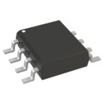 DMN4026SSD-13

The activity of extra discounts on wholesale prices is in full swing…
Please fill in your contact information and we will send you the latest wholesale price list.





