 ChipApex | Global Electronic Components Supplier
SEARCH
Search Product
Search Post
— IC芯片 | 连接器 | 传感器 | 被动器件 —
Search productSearch post
— IC芯片 | 连接器 | 传感器 | 被动器件 —
Consult the customer manager about the wholesale price.
consultation hotline:86-132-6715-2157
email:[email protected]
Contact the product manager for consultation. One-stop consultation is available.
Do you want a lower wholesale price? Please send us your inquiry and we will reply immediately.
The GT50N322A is a Silicon N-Channel IGBT from Toshiba's fifth generation, designed for voltage resonance inverter switching applications. It features an integrated Fast Recovery Diode (FRD) between the emitter and collector. Key electrical parameters include a collector-emitter voltage of 1000 V, a DC collector current of 50 A, and a maximum power dissipation of 156 W at 25°C case temperature. The device exhibits a typical saturation voltage of 2.2 V at 60 A and a fall time of 0.10 μs. It operates within a junction temperature range up to 150°C and utilizes a TO-3P package.
Verify RoHS compatibility directly with the manufacturer or authorized distributor, as the datasheet specifies contacting sales representatives for product-specific details regarding restricted substances. Ensure the ordering suffix matches the required lead-free finish specifications. Confirm that the component meets all applicable safety standards for the intended general electronics application before finalizing procurement.
Select this component for designs requiring high blocking voltage and fast switching speeds. Consider the thermal resistance of 0.8 °C/W when designing heat sinks. Verify that the gate drive circuit can handle the specified ±25 V limit. Evaluate the safe operating area curves to ensure reliable operation under pulsed load conditions and varying case temperatures.
This part belongs to Toshiba's fifth-generation discrete IGBT lineup. It is engineered specifically for voltage resonance inverter applications, distinguishing it from standard hard-switching devices. The inclusion of an internal FRD simplifies circuit topology by eliminating the need for external anti-parallel diodes in certain configurations.
No public confirmed substitute part numbers are available in the provided documentation. Cross-referencing requires matching the 1000 V rating, 50 A current capacity, TO-3P package, and specific switching characteristics like fall time and saturation voltage.
The typical reverse recovery time (trr) is 0.8 μs when measured at a forward current of 15 A and a di/dt of -20 A/μs.
The absolute maximum collector-emitter voltage (VCES) is rated at 1000 V.
The collector-emitter saturation voltage increases as the case temperature rises, as shown in the VCE(sat) vs. Tc characteristic curve in the datasheet.
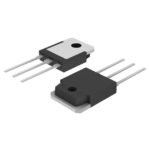 GT50N322A
The activity of extra discounts on wholesale prices is in full swing…
Please fill in your contact information and we will send you the latest wholesale price list.





