ChipApex | Global Electronic Components Supplier

SEARCH
Search Product
Search Post
— IC芯片 | 连接器 | 传感器 | 被动器件 —
Search productSearch post
— IC芯片 | 连接器 | 传感器 | 被动器件 —
Consult the customer manager about the wholesale price.
consultation hotline:86-132-6715-2157
email:[email protected]
Contact the product manager for consultation. One-stop consultation is available.
Do you want a lower wholesale price? Please send us your inquiry and we will reply immediately.
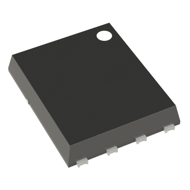
IPG20N06S3L-35 is listed in the FET, MOSFET Arrays range at ChipApex. The manufacturer field lists Infineon Technologies. Its product description is MOSFET 2N-CH 55V 20A 8TDSON. Review the specifications below when checking this part for your BOM.
The IPG20N06S3L-35 is a dual N-channel logic level enhancement mode MOSFET from the OptiMOS-T series. It features a PG-TDSON-8-4 package with a maximum drain-source voltage of 55 V and a continuous drain current of 20 A per channel at 25 °C. The device has a maximum on-state resistance of 35 mΩ at VGS=10 V and 62 mΩ at VGS=5 V. Total gate charge is typically 18 nC, and power dissipation reaches 30 W per channel. It operates between -55 °C and +175 °C.
Verify the specific ordering suffix against official Infineon documentation to confirm exact electrical tolerances and packaging specifications. Ensure that the procurement source provides valid traceability data consistent with the manufacturer's quality standards. Cross-reference the component marking code with the datasheet product summary to validate authenticity before integration into production lines.
Select this component when a dual-channel solution is required within a limited footprint. The logic level threshold allows efficient driving from standard low-voltage logic interfaces. Evaluate the thermal resistance characteristics against the specific PCB copper area available for heat dissipation to ensure safe operating limits are maintained under continuous load conditions.
This part belongs to the OptiMOS-T family of power transistors designed by Infineon Technologies. It utilizes silicon technology optimized for low conduction losses and robust switching performance. The device integrates two independent channels within a single leadless package to minimize board space while maintaining high current handling capabilities for modern power electronics applications.
IPG20N06S3L-35A
The absolute maximum gate-source voltage is ±16 V.
Yes, the datasheet specifies it is 100% avalanche tested with a single pulse avalanche energy rating of 55 mJ at 10 A.
The maximum RDS(on) is 62 mΩ at VGS=5 V and decreases to 35 mΩ at VGS=10 V.
Explore related parts through FETs, MOSFETs, Transistors, Discrete Semiconductor Products, all product categories.
 IPG20N06S3L-35

The activity of extra discounts on wholesale prices is in full swing…
Please fill in your contact information and we will send you the latest wholesale price list.