ChipApex | Global Electronic Components Supplier
SEARCH
Search Product
Search Post
— IC芯片 | 连接器 | 传感器 | 被动器件 —
Search productSearch post
— IC芯片 | 连接器 | 传感器 | 被动器件 —
Consult the customer manager about the wholesale price.
consultation hotline:86-132-6715-2157
email:[email protected]
Contact the product manager for consultation. One-stop consultation is available.
Do you want a lower wholesale price? Please send us your inquiry and we will reply immediately.
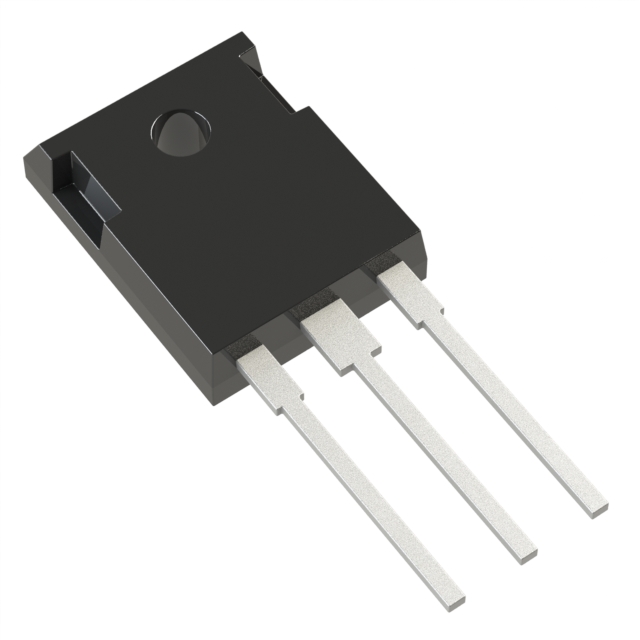
The NGW50T65H3DFPQ is a third-generation Insulated-Gate Bipolar Transistor (IGBT) from Nexperia, utilizing carrier stored trench-gate and field-stop structures. It operates with a collector-emitter voltage of 650 V and a continuous collector current of 50 A at Tc = 25 °C. The device supports a maximum junction temperature of 175 °C and features a fully rated silicon diode. Key electrical parameters include a typical saturation voltage of 1.72 V at 50 A and 25 °C, and a gate threshold voltage ranging from 4.3 V to 5.7 V. Thermal resistance from junction to case is typically 0.37 K/W for the IGBT.
Verify the specific ordering suffix against the manufacturer's official documentation to confirm package type and reel specifications. Confirm RoHS compliance status through the latest datasheet revision. Ensure that the intended application does not exceed the absolute maximum ratings defined in the limiting values section. Cross-reference the part number with the most recent product data sheet to validate any changes to pinning or thermal characteristics before finalizing procurement orders.
Select this component for high-voltage, hard-switching industrial power inverter applications requiring efficient switching at high frequencies. The device is suitable for designs needing a maximum junction temperature of 175 °C. Consider the thermal resistance values when designing heatsinking solutions. Verify that the gate drive requirements align with the specified threshold voltage and internal gate resistor values for optimal switching performance.
This IGBT belongs to Nexperia's NGW series, which utilizes third-generation technology combining carrier stored trench-gate and field-stop structures. The series is designed for high-voltage, high-frequency industrial power inverter applications. The TO-247-3 package provides a robust mechanical solution for heatsink mounting, supporting high power dissipation requirements in compact designs.
Direct replacements must match the 650 V rating, 50 A current capability, and TO-247-3 package. Verify compatibility of switching losses and thermal resistance. Check if alternative devices offer similar tight parameter distributions for parallel operation. Ensure the replacement includes an integrated fast recovery diode if required by the circuit topology.
 NGW50T65H3DFPQ
The activity of extra discounts on wholesale prices is in full swing…
Please fill in your contact information and we will send you the latest wholesale price list.