 ChipApex | Global Electronic Components Supplier

SEARCH
Search Product
Search Post
— IC芯片 | 连接器 | 传感器 | 被动器件 —
Search productSearch post
— IC芯片 | 连接器 | 传感器 | 被动器件 —
The trend of science and technology is changing rapidly.
UART stands for universal asynchronous receiver-transmitter. It is hardware that sends and receives serial data without a shared clock line, typically using agreed baud rate and frame settings. People often call this the UART protocol, although UART framing alone does not define message meaning, connector pinout or electrical signaling standard.
For a reliable link, both ends need compatible frame settings and electrical levels. Software must also define how bytes form messages and how errors are handled. A terminal displaying characters is useful evidence of basic communication, but it does not prove that every message arrives intact under load.
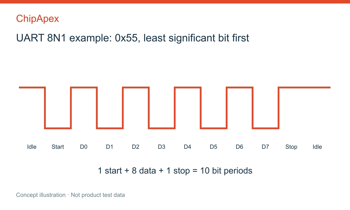
A conventional non-inverted UART line idles high. A low start bit tells the receiver that a frame is beginning. Data bits follow, usually least significant bit first, then an optional parity bit and one or more stop bits. The receiver uses its own timing to sample the incoming line.
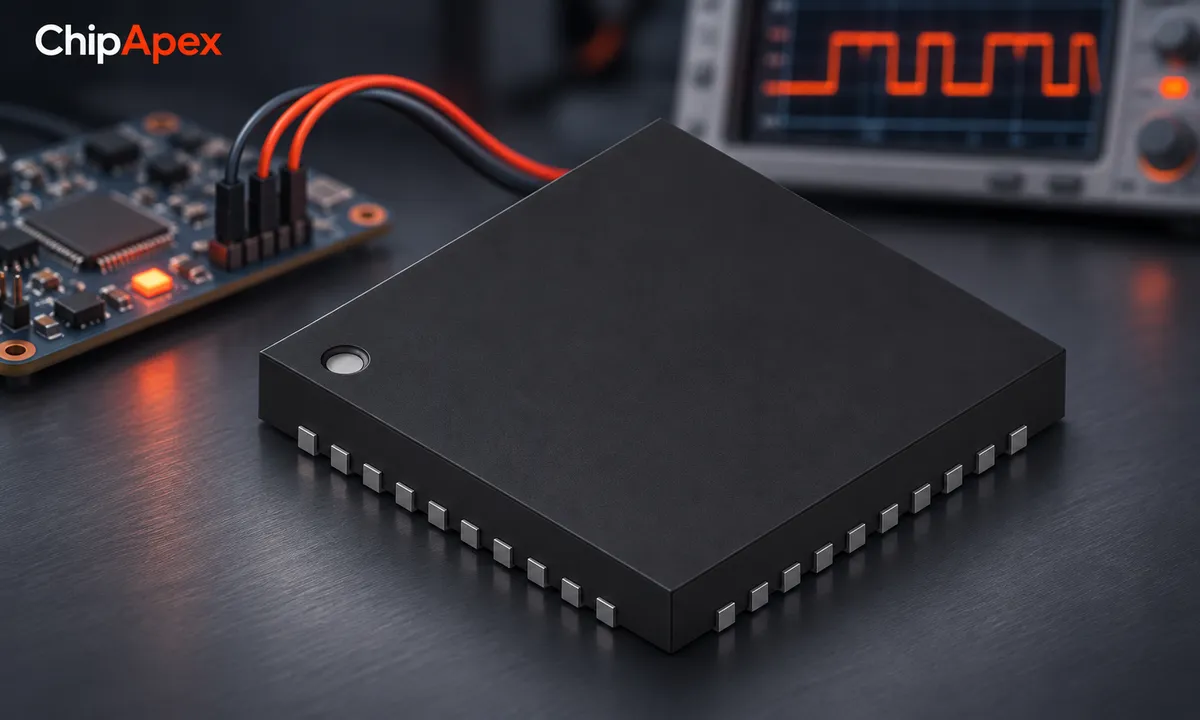
The common setting 8N1 means eight data bits, no parity and one stop bit. Including the start bit, it takes ten bit periods to transmit one eight-bit data value. At 115200 baud, the theoretical continuous 8N1 payload rate is therefore 11520 bytes per second before message overhead and gaps.
When comparing uart devices, check supported word lengths, parity modes, baud generation and buffering. These capabilities vary between integrated microcontroller peripherals and external UART components. Analog Devices' UART overview explains framing and the role of the transmitter and receiver.
Baud rate describes symbol rate. For ordinary binary UART signaling, one symbol carries one bit, so the baud and bit-rate numbers match. Payload throughput is lower because start, stop, parity and application framing consume time.
Both ends must agree on the nominal rate, data bits, parity and stop-bit format. Their clocks also have finite error. The allowed mismatch depends on receiver sampling, frame length and implementation; do not assume one universal percentage applies to every device.
A baud-divider setting may introduce error even with an accurate oscillator. Check the actual achievable rate from the peripheral clock and divider. Temperature-dependent clock drift can explain a link that works on the bench but becomes unreliable in a different environment.
UART describes framing and hardware behavior. RS-232 and RS-485 describe electrical interfaces with different signaling arrangements. A microcontroller's UART pins are often logic-level signals and should not be connected directly to an incompatible external interface.
| Connection | What to verify |
|---|---|
| Logic-level UART | Supply levels, input thresholds, absolute limits and ground reference |
| RS-232 | Suitable transceiver, signal polarity and connector wiring |
| RS-485 | Differential transceiver, direction control, topology and termination |
| USB-to-UART adapter | Adapter output level, driver configuration and signal-pin identity |
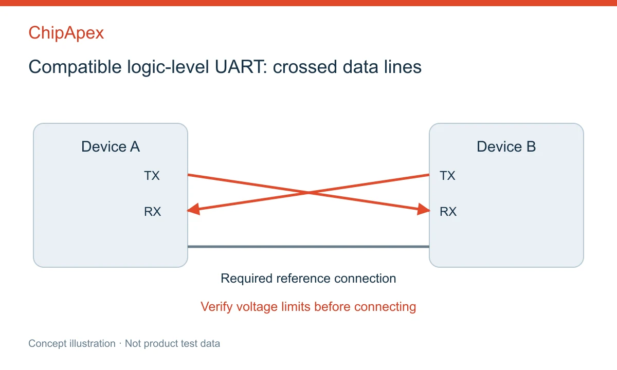
For a simple compatible logic-level link, connect one device's TX to the other's RX and vice versa. Establish the required reference connection. Check input voltage limits: a 3.3 V label does not prove that a pin tolerates 5 V. Use a suitable interface circuit where levels or isolation requirements differ.
The Rohde & Schwarz UART explanation provides useful context for observing UART signals and distinguishing the serial format from its electrical implementation.
A UART delivers a stream of received bytes. It does not inherently identify which bytes form a command, verify a packet checksum or acknowledge a transaction. Those functions belong to the application protocol or another layer above UART framing.
Define message boundaries using a suitable length field, delimiter or other scheme. Specify byte order for multibyte values, permitted payloads, timeouts and recovery after a partial message. If a delimiter can appear inside data, the encoding needs a way to distinguish it from a boundary.
Parity can detect some bit errors but cannot establish complete message integrity. Applications may need a checksum or CRC, sequence numbering and retry rules according to their consequences and timing requirements. Avoid inventing a custom reliability scheme without considering how it recovers after dropped or inserted bytes.
A receiver may be unable to service incoming data fast enough during other work. Hardware FIFOs, interrupts or DMA can help, but buffer capacity is finite. An overrun can discard data even when the electrical waveform and baud rate are correct.
Hardware flow control commonly uses RTS and CTS, with behavior defined by the particular devices and driver settings. Software flow control uses control characters and may conflict with unrestricted binary payloads unless the protocol accounts for them. Confirm support at both ends instead of enabling one side only.
For sustained transfers, calculate worst-case input rate and the longest interval during which software cannot service the receiver. Test at that condition, including logging, storage and other interrupts. A short interactive terminal test rarely exercises the worst case.
If no data arrives, first check power, reference connection, TX/RX routing and interface voltage. Then verify the actual bit timing and frame format with appropriate test equipment. A logic analyzer's decode settings must match the signal; an incorrect decoder configuration can make a valid waveform look corrupt.
Garbled text often suggests a rate or format mismatch, but line noise, inversion or a wrong voltage interface can produce similar symptoms. Missing blocks under load suggest buffering or flow-control issues. A valid byte stream with wrong values can instead reflect application parsing or byte-order mistakes.
TX and RX are the two common data signals for full-duplex communication, but the electrical connection usually also needs an appropriate reference or an isolated interface arrangement. Flow control can add more signals. A two-wire description should not be interpreted as permission to ignore grounding and voltage compatibility.
UART is one form of serial communication hardware and framing. Other serial interfaces include SPI, I2C and many differential or packet-based systems. The word serial alone does not identify timing, electrical levels or message format, so specify the actual interface when selecting components or connecting equipment.
They need to agree closely enough for the receiver to sample each frame correctly. Some hardware supports automatic baud detection, but that is a device-specific feature with its own requirements. Otherwise, configure compatible rates and verify actual clock and divider error at both ends.
Conventional asynchronous UART does not use a shared clock line. The receiver detects the start bit and times subsequent samples using its own clock. That is why baud-rate agreement and clock accuracy matter. Some multifunction serial peripherals support synchronous modes, but those are separate operating arrangements.
There is no universal distance for bare UART logic. Cable capacitance, signaling voltage, baud rate, noise, grounding and driver characteristics all matter. For longer or electrically demanding links, use a suitable physical-layer transceiver and design the cable system accordingly rather than relying on a generic distance claim.
For a ChipApex inquiry, provide channel count, required baud rates, host bus, supply voltage, FIFO and flow-control needs, package and operating temperature. Identify the external electrical interface separately. These requirements help select a component for the complete communication path rather than only the UART label.
Select a DC-DC converter by input range, topology, isolation and temperature. Compare ripple, efficiency and load limits before choosing a component.
View details
Practical MCU selection guide for engineers: compare STM32, ESP32 & NXP, avoid counterfeits, and ensure supply chain reliability. Authored by ChipApex FAE.
View details
Select MOV varistors by continuous voltage, clamping behavior, surge waveform and repetition. Check thermal disconnection, fuse coordination and replacements.
View details
Select a bridge rectifier by reverse voltage, capacitor charging current, startup surge and cooling. Work through a stated DC voltage and ripple example.
View details
The activity of extra discounts on wholesale prices is in full swing…
Please fill in your contact information and we will send you the latest wholesale price list.

