 ChipApex | Global Electronic Components Supplier

SEARCH
Search Product
Search Post
— IC芯片 | 连接器 | 传感器 | 被动器件 —
Search productSearch post
— IC芯片 | 连接器 | 传感器 | 被动器件 —
The trend of science and technology is changing rapidly.
A metal oxide varistor, or MOV, is a nonlinear protection component that conducts more current as the voltage across it rises, helping limit transient overvoltage. Select an MOV by continuous working voltage, voltage-current behavior, surge waveform and repetition, temperature and failure-protection requirements. A voltage marking or joule rating alone cannot establish suitability.
An MOV is normally part of a protection system. Source impedance, wiring, the protected load and any disconnecting devices affect what voltage and energy the system experiences. Begin with the supply and fault conditions before comparing catalog parts.
Under normal specified operating conditions, an MOV has relatively high impedance and limited leakage. As the voltage increases, its nonlinear characteristic allows more current to flow. The voltage across it continues to depend on current, temperature and device characteristics; it is not an ideal fixed-voltage clamp.
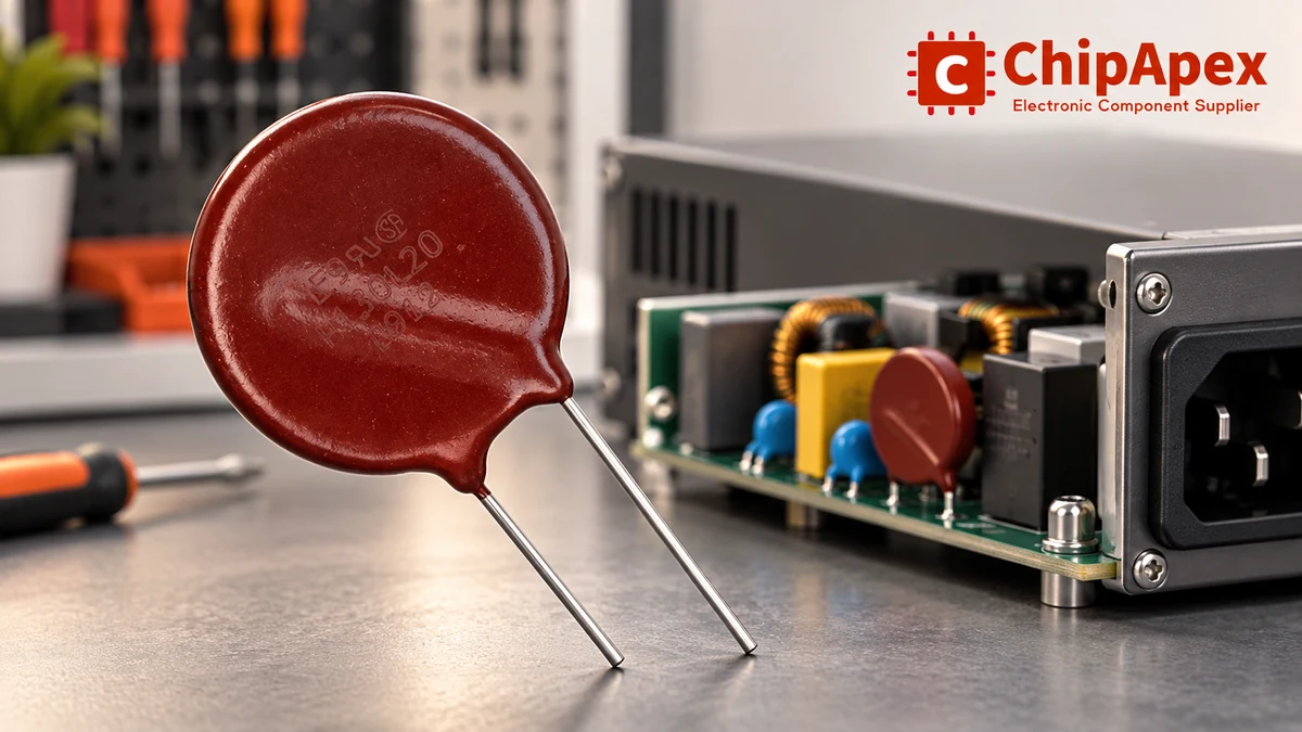
Many common MOVs are bidirectional. Confirm the selected device’s characteristic and connection requirements rather than assuming that every overvoltage-protection component behaves the same way.
When reviewing varistors, consider where surge current flows after the MOV conducts. A long connection can add inductive voltage during a rapidly changing current. The voltage at the protected component can therefore differ from the voltage measured directly at the MOV’s terminals.
Keep the protection path short and appropriate to the circuit, while maintaining required separation and insulation. Layout is part of the protection design. An MOV placed somewhere on the board does not guarantee that every connected input sees the intended limiting voltage.
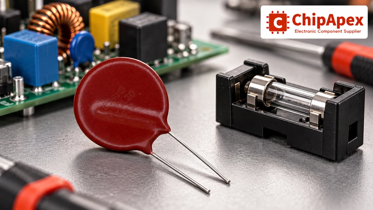
Continuous working voltage, varistor voltage and clamping voltage describe different conditions. Compare them using the definitions and test conditions in the exact datasheet.
| Specification | What it describes | What to check |
|---|---|---|
| Maximum continuous AC or DC voltage | Permitted sustained operation under specified conditions | AC/DC convention, supply tolerance, temperature and abnormal operating conditions |
| Varistor voltage | Voltage measured at a specified small test current | Test current, tolerance and temperature |
| Clamping voltage | Limiting voltage at a stated surge current and waveform | Current level, waveform, tolerance and the protected circuit’s withstand capability |
A varistor voltage measured at a small DC test current is not a promise that the MOV will hold a surge to that voltage. At a much higher surge current, the limiting voltage can be substantially higher. Use the stated test conditions and the relevant voltage-current information.
The manufacturer’s MOV selection white paper explains these selection parameters and the importance of transient duration. Read them together rather than comparing isolated values from different catalog columns.
Start with the highest sustained voltage the component will see in its intended operating conditions. Include source tolerance and the appropriate AC or DC specification. A nominal supply label may omit the range that matters to leakage, heating and life.
For a sinusoidal source, RMS and peak voltage describe different quantities. Do not compare an AC RMS working-voltage rating directly with a DC rating and assume that the two are interchangeable. Follow the manufacturer’s definitions for the device.
Then identify credible abnormal conditions. A temporary overvoltage lasting much longer than a specified surge pulse can heat an MOV differently from a brief transient. A protection plan needs to consider that duration and the available source current, not just the desired clamping response.
At the input of an industrial ac to dc converter, coordinate the protection with the converter’s input requirements and the equipment’s intended installation. A part that suits one source and enclosure may be unsuitable when voltage tolerance, fault energy or ambient temperature changes.
A surge-current rating comes with a waveform and specified conditions. An 8/20 µs current pulse and a longer pulse with the same peak are different stresses. A quoted peak current without its waveform is incomplete information for selection.
Energy is the time integral of instantaneous voltage multiplied by current. A simplified example illustrates why duration matters: if a device were to experience a rectangular 100 A pulse at an assumed constant 500 V for 20 µs, the calculated energy would be 1 J. A real surge is not that rectangular pulse, and an MOV’s voltage changes with current. The example explains units; it is not a test or a selection rule.
Compare actual pulse requirements with the manufacturer’s allowed pulse-duration and repetition information. Temperature, initial conditions and the permissible change in characteristics can affect the stated capability. Avoid mixing a single-event maximum from one test with a repetitive operating requirement from another.
For a protected DC bus containing aluminum electrolytic capacitors, evaluate the capacitor’s voltage stress at its own terminals. The MOV’s catalog clamping value, connection inductance and the rest of the network all affect whether that stress is acceptable.
MOV characteristics can change after electrical stress. The acceptable number and size of surge events depends on the particular device and conditions. A component’s ability to survive one specified pulse does not establish an unlimited repetitive life.
Review repeated-pulse information, operating temperature and how the application identifies a degraded or disconnected protection path. Some designs need an end-of-life indication or a defined maintenance method. A device that has disconnected can leave the equipment operating without the original level of protection.
Leakage and heating also need attention under sustained voltage. If an MOV conducts excessively during an abnormal condition, temperature can rise and create a hazardous failure path. A static appearance check or a simple resistance reading does not establish remaining surge capability.
When replacing a damaged MOV, investigate the source event and nearby protection components. Installing a visually similar disk without checking its full specification can recreate the original failure or leave the protected equipment exposed to a different limiting voltage.
An MOV is commonly connected across the nodes whose transient voltage it is intended to limit. If an abnormal condition causes prolonged conduction, the design may need to disconnect that path before unacceptable heating occurs. The disconnection method and its placement must suit the equipment and applicable requirements.
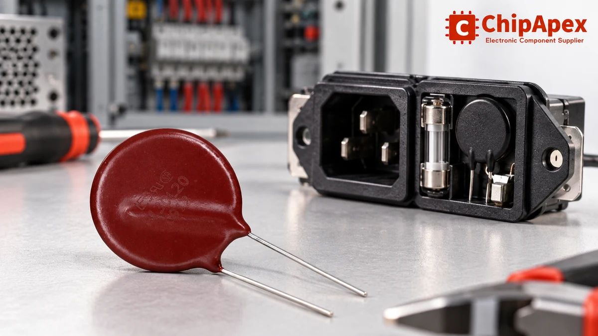
Conventional electrical fuses respond according to their current-time behavior and available fault current. They may not respond to every MOV overheating condition in the required way. Evaluate the actual coordination rather than assuming that any upstream fuse covers every fault.
A suitably selected thermal fuse or an integrated thermally protected device can address temperature-related disconnection in an appropriate design. Thermal coupling, electrical rating, clearances and the complete failure sequence need to be reviewed. A loose thermal cutoff somewhere in the enclosure does not demonstrate effective MOV protection.
Thermally protected varistor constructions illustrate one approach to combining limiting and disconnecting functions. Their availability does not mean that every arrangement built from separate parts meets the same performance or safety requirements. Check the exact part’s approvals and the requirements for the finished equipment.
MOVs and tvs diodes can both limit transient voltage, but their characteristics, available packages and intended uses differ. Select using continuous voltage, voltage-current behavior, waveform capability, leakage, capacitance, temperature and the failure-protection arrangement.
For a signal interface, capacitance and leakage can affect normal operation as well as protection. For a power input, source energy and sustained abnormal conditions may dominate the review. The broad label “surge protection” does not make two devices interchangeable.
In some designs, several protection stages coordinate to manage different parts of the event. That coordination requires analysis of wiring, source impedance, timing and the stress seen by each stage. Adding more protection components without that review can move stress to an unsuitable location.
Record the nominal and maximum continuous supply voltage, AC/DC operation, expected transient waveforms, surge repetition and temperature range. Specify the acceptable voltage at the protected component, not only the MOV’s own test-point value.
Include physical constraints such as disk or package dimensions, lead pitch, spacing, mounting and thermal coupling. Request the full ordering code because suffixes may identify tolerance, coating, lead or protection features. If approvals matter, identify the required certification and scope without assuming that a component approval certifies the complete equipment.
No. Varistor voltage is measured at a specified test current, while maximum continuous working voltage describes permitted sustained operation under stated conditions. Clamping voltage is another parameter measured during a specified surge. Check the datasheet’s definitions, tolerances and test conditions before using any of these values in a protection specification.
No. Energy rating needs to be considered with pulse waveform, duration, peak current, repetition and temperature. The clamping behavior must also be compatible with the protected circuit, and continuous working voltage must suit the source. Two parts with the same energy figure can have different limiting behavior and different allowed operating conditions.
Its limiting voltage depends on the current through it and the specified device characteristics. Connection inductance and the rest of the circuit can add voltage at the protected component. Use the relevant voltage-current data and surge conditions, then evaluate the complete installation. A single catalog clamping value is tied to a particular test point.
No universal lifetime follows from a single surge rating. Repeated electrical stress can alter an MOV’s characteristics, and permitted repetitions depend on the device, pulse conditions and temperature. Review the manufacturer’s repetitive-pulse information and the equipment’s maintenance or end-of-life strategy. A device that still looks intact has not thereby passed a surge-capability test.
The required protection arrangement depends on the source, fault conditions, device construction and equipment requirements. Some devices integrate a thermally activated disconnect; other designs use separately coordinated protection. Evaluate prolonged overvoltage and heating as well as brief surges. Do not assume that a conventional upstream fuse necessarily responds to every overheating condition fast enough.
Only after evaluating both devices in the actual circuit. Compare continuous voltage, limiting behavior at the relevant current, waveform capability, leakage, capacitance, temperature and failure protection. Package similarity or the shared description “transient suppressor” does not establish interchangeability. A replacement also needs suitable connections, clearances and compatibility with the rest of the protection network.
For a ChipApex enquiry, provide the original part number or these electrical and installation requirements, quantity and any documentation needs. When considering an alternate, compare the actual datasheet conditions and protection coordination. A similar body color, disk size or printed number is a starting point for identification, not an engineering approval.
A pressure transducer turns pressure into an electrical signal that a controller can read. Inside the device, a sensing element responds to pressure; the electronics then provide a specified voltage, current, or digital output. The output format m...
View details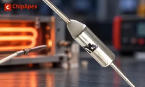
Understand thermal fuse operation, Tf, Th and Tm, electrical ratings and mounting. Check temperature limits and replacement requirements for your design.
View details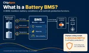
A battery BMS, or battery management system, monitors a battery and controls how it is used within defined operating limits. It measures conditions such as cell voltage, pack current and temperature. Depending on the design, it can also balance ce...
View details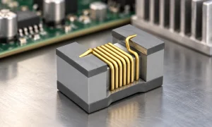
An inductor is approximately linear only over a specified operating range. In the ideal model, its inductance stays constant and voltage equals inductance times the rate of current change. A real magnetic core can approach saturation as current ri...
View details
The activity of extra discounts on wholesale prices is in full swing…
Please fill in your contact information and we will send you the latest wholesale price list.

