 ChipApex | Global Electronic Components Supplier

SEARCH
Search Product
Search Post
— IC芯片 | 连接器 | 传感器 | 被动器件 —
Search productSearch post
— IC芯片 | 连接器 | 传感器 | 被动器件 —
The trend of science and technology is changing rapidly.
An inductor is approximately linear only over a specified operating range. In the ideal model, its inductance stays constant and voltage equals inductance times the rate of current change. A real magnetic core can approach saturation as current rises, reducing inductance. Temperature, frequency, and winding resistance also affect circuit behavior.
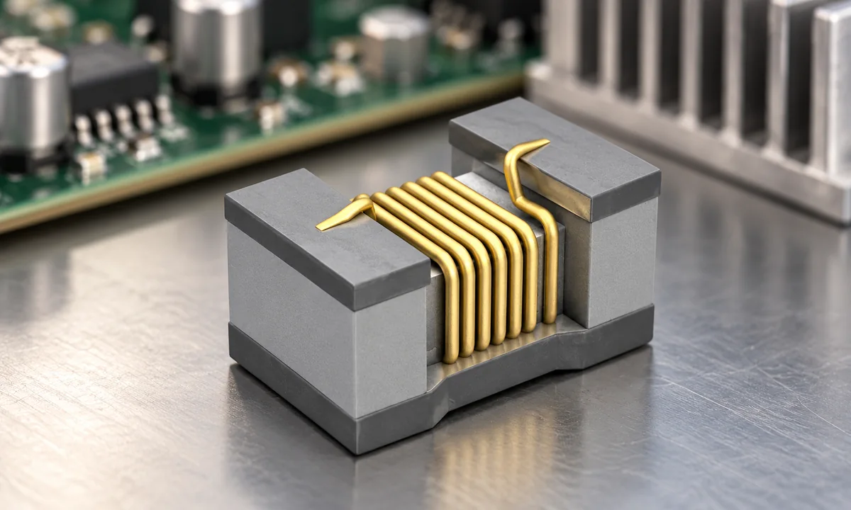
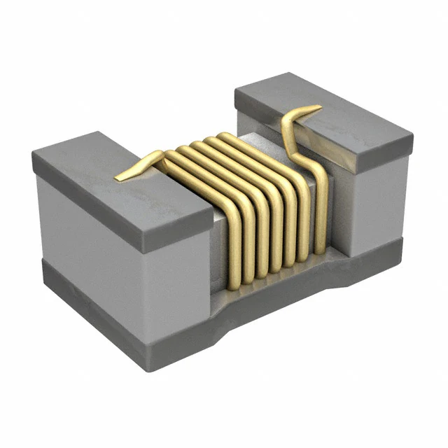
For a fixed inductance, doubling a current change doubles the corresponding magnetic-flux change. The simple equation v = L × di/dt is useful for estimating ripple in a power converter. It assumes L is effectively constant over that current swing. Real inductors are specified with operating limits because that assumption eventually fails.
As DC bias pushes a magnetic core toward saturation, its incremental inductance can fall. Under the same applied voltage, current then changes faster. In a switching regulator, that can increase ripple and peak current when the load is already high. The effect is gradual for some core materials and steeper for others; there is no universal current at which every inductor suddenly stops working.
Look for the manufacturer's inductance-versus-current curve. A saturation-current value often uses a stated percentage drop in L, and that percentage varies among datasheets. Rated current may instead refer to temperature rise. These are different constraints; compare both.
The winding has resistance, so current produces heat. Core loss rises with the actual waveform and frequency. Heating can change resistance and magnetic behavior. A nominal inductance measured at a small test signal may therefore differ from the effective value in a converter carrying a DC load plus AC ripple.
The broader coil choke family includes parts intended for filtering or energy storage. A component chosen for EMI suppression is not automatically suitable as a converter's storage inductor.
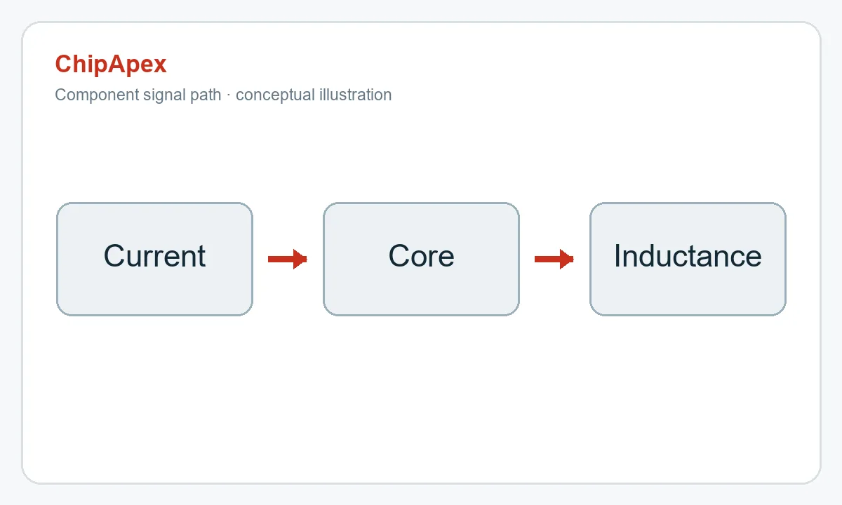
Calculate the maximum DC current and ripple-current peak at the worst operating condition. Compare that peak with the DC-bias curve and thermal rating at your enclosure temperature and airflow. DCR, tolerance, self-resonant behavior, and footprint may narrow the shortlist. ChipApex can help identify the matching datasheet when you have a target value and current range.
They avoid ferromagnetic-core saturation, but winding resistance, parasitic capacitance, and temperature still make the real component depart from an ideal inductor.
Usually not. One may be based on inductance loss and the other on temperature rise. Read the definition beside each number.
That depends on the circuit and the datasheet definition. Inductance may fall and current ripple may rise; verify performance and temperature rather than assuming the rating is a harmless boundary.
The core's magnetic permeability falls as it approaches saturation, so the same winding stores less incremental flux for a given current change.
The inductance-versus-DC-bias curve, together with temperature-rise information, shows how the part behaves at the converter's operating current.
Understand RF attenuator dB values, fixed and programmable types, impedance, power limits and noise tradeoffs before choosing parts for an RF signal path.
View details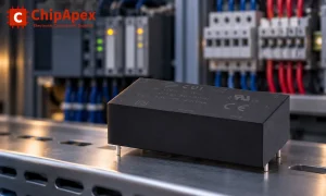
Choose an AC to DC converter by input range, output demand, isolation, efficiency and thermal derating. Compare architectures and check installation needs.
View details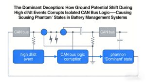
Ground potential shift during high dI/dt regen braking causes isolated CAN receivers to output false dominant states, locking EV BMS networks. Discover robust solutions like TJA1044GT/3Z + common-mode filtering validated by ChipApex.
View details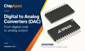
Learn how digital to analog converters work, compare DAC types and selection criteria, and send your part number or BOM to ChipApex for a component quote.
View details
The activity of extra discounts on wholesale prices is in full swing…
Please fill in your contact information and we will send you the latest wholesale price list.

