 ChipApex | Global Electronic Components Supplier

SEARCH
Search Product
Search Post
— IC芯片 | 连接器 | 传感器 | 被动器件 —
Search productSearch post
— IC芯片 | 连接器 | 传感器 | 被动器件 —
The trend of science and technology is changing rapidly.
An AC to DC converter changes an alternating input into a direct-current output. A complete power supply may include rectification, filtering, voltage regulation, isolation and protection. The right choice depends on the load, input range, thermal environment and installation. Its usable output power can be lower than the headline rating under demanding conditions.
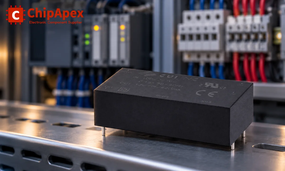
Start with output voltage and current at the equipment, including startup and transient demands. A controller drawing 0.8 A continuously and briefly demanding 1.6 A presents a different requirement from a steady resistive load. Write down how long the peak lasts and how often it occurs.
Power is Pout = Vout × Iout. A hypothetical 24 V, 2 A load therefore requires 48 W continuously. That arithmetic is only the beginning: the selected supply must provide the required current at the lowest intended input voltage and the hottest intended installation temperature.
A useful specification also states output-voltage tolerance, allowed ripple, startup behavior and what the equipment should do during a brownout. ChipApex's industrial ac to dc converter category covers a sourcing stage; compatibility still requires the individual module's datasheet.
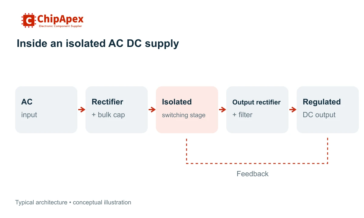
Many isolated switching supplies first protect and filter the AC input, rectify it into a DC bus, then switch that bus at a higher frequency. An isolation transformer transfers energy to the output, where rectification and filtering produce DC. Feedback controls the delivered voltage or current.
The order differs in a traditional linear supply. A line-frequency transformer usually reduces and isolates the AC before a rectifier, reservoir capacitor and linear regulator. The transformer can be large, while regulator dissipation rises with the voltage it must drop.
The rectifier stage and a complete converter have different responsibilities. A diode bridge rectifier establishes polarity. It does not, by itself, regulate the voltage, limit every fault or provide mains isolation.
| Architecture | Where it can fit | What requires attention |
|---|---|---|
| Transformer plus linear regulation | Applications where noise and circuit simplicity justify size and heat | Transformer size, dropout margin and regulator dissipation |
| Isolated flyback | Compact isolated supplies and auxiliary rails | Peak currents, transformer design, leakage-energy management and output ripple |
| Forward or bridge-based conversion | Designs with power and current requirements that justify a different energy-transfer arrangement | Magnetics reset, switching control and component stress |
| Resonant conversion, such as LLC | Designs pursuing efficient high-frequency operation over a defined range | Load range, control behavior and magnetic-component design |
| Nonisolated offline conversion | Restricted applications where the complete product design permits it | Output remains electrically related to mains; system insulation and access requirements govern suitability |
These are design families, not fixed wattage bands. Power alone does not determine the topology. Input range, isolation, transients and cost can change the choice. The manufacturer's power-supply design brief sets out these specification questions before topology selection.
For most equipment buyers, comparing complete modules is more useful than redesigning the switching stage. A module still needs the specified external parts, cooling and installation conditions. A controller IC, open-frame supply and encapsulated board module are different purchasing items.
An input marked for a wide AC range does not always guarantee full output power at every voltage. Some supplies require reduced output at low input voltage. Input current increases as voltage falls for the same output power, and the thermal burden changes.
Temperature can impose a second limit. Check the derating curve for ambient or case temperature, mounting orientation, airflow and cooling method. A forced-air rating may be unavailable in a sealed, naturally cooled enclosure.
As an illustrative calculation, a 60 W supply with an allowed-output factor of 0.70 at a particular operating condition provides 42 W at that condition. It would not cover the 48 W continuous load described earlier. Use the actual combined operating envelope; multiplying unrelated derating factors is valid only if the manufacturer specifies that method.
The manufacturer's derating explanation describes why both temperature and input voltage can reduce available power. A fixed percentage of spare capacity cannot replace those curves.
Efficiency is output power divided by real input power. For a given output, the lost power becomes heat:
Ploss = Pout × (1 / efficiency − 1)
A hypothetical 48 W output at 88% efficiency produces about 6.5 W of losses. At 92%, it produces about 4.2 W. Those are calculated examples, not measurements of a ChipApex product.
Read efficiency curves at the intended input and load. A full-load headline value can hide different behavior during standby or low-load operation. The manufacturer's efficiency discussion explains the effects of input voltage, output model and load.
Ripple is the periodic variation on the DC output. Switching spikes and broadband noise are separate concerns. Compare measurements using the datasheet's bandwidth, probe arrangement and output-capacitor conditions. A long oscilloscope ground lead can add measurement artifacts.
Transient response describes what happens when the load changes. Check both voltage deviation and recovery time against the equipment's tolerance. A supply with acceptable average voltage may still reset a processor during a load step.
An isolation test voltage is only one part of an insulation specification. Working voltage, insulation category, creepage and clearance, leakage current and the final product's requirements also matter. Component approval does not automatically establish compliance of the assembled equipment.
Protection behavior needs equally close reading. An overcurrent event may cause constant-current operation, hiccup restart, foldback or a latched shutdown. These responses affect motor starting, capacitive-load charging and recovery after a fault. Verify which features are actually specified.
Power factor describes how effectively input apparent power becomes real power; efficiency describes losses between input and output. They are different quantities. Power factor correction shapes input behavior. Whether it is required depends on the equipment class, market and applicable harmonic limits, so avoid a universal wattage rule.
In a custom design, the input stage may need a fuse, surge suppression and suitable inrush limiting. An NTC thermistor can serve that duty in some circuits, but it must be rated for the charging event and normal current. A sensing thermistor cannot be selected merely because it is NTC.
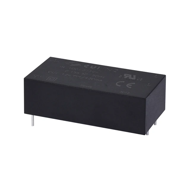
Before comparing quotations, establish the mechanical format: board mount, chassis, DIN rail or external adapter. Check pin pitch or terminal positions, enclosure space, cable polarity, mounting requirements and service access. Similar output ratings do not establish mechanical interchangeability.
For a multi-rail system, one AC DC supply may feed local dc dc converters. This can be practical when different boards need different voltages, but distribution losses, sequencing and grounding still require review.
Include the external components required by the module's reference circuit in the cost and space estimate. Ask for the exact manufacturer's datasheet and the relevant approval documentation for the complete part number. Availability and suitability should be confirmed for that item rather than inferred from a family name.
An external AC adapter is one packaged form of AC to DC conversion. The same function also appears in board-mounted modules, chassis supplies and integrated power circuits. The enclosure, connections, protection and approvals differ. Check the installation requirements along with electrical ratings when replacing an adapter with another format.
A regulated voltage supply with a higher available current can often serve a lower-current load if voltage, polarity, regulation and protection behavior match. The load normally determines the current drawn. Constant-current supplies follow a different control objective. Also check minimum-load requirements and startup behavior before treating two supplies as interchangeable.
No fixed equality applies. A capacitor-input bridge charges toward the AC peak minus diode drops, while the voltage falls between peaks under load. The AC RMS value, transformer regulation, capacitance and current all affect the result. A regulated converter is needed when the load requires a controlled 12 VDC rail.
Some models have an explicitly specified DC input range. Others are approved and designed only for AC use. A bridge at the input does not establish DC compatibility of fuses, protection or approvals. Use the manufacturer's published input specification for the exact model and intended application.
There is no percentage that suits every design. Start with continuous demand, startup peaks, transients and expected expansion. Then apply the manufacturer's allowed power under the actual input, temperature and cooling conditions. A larger nameplate rating helps only when its derated operating capability covers those requirements.
For a ChipApex inquiry, include the required input range, output voltage, continuous and peak current, ambient temperature, mounting format and quantity. Add the existing part number and approval requirements when replacing a supply.

Find out when a bare shock switch needs a pull resistor, when an MCU internal pull-up is enough, and why sensor modules and piezo elements differ.
View details
Ground potential shift during high dI/dt regen braking causes isolated CAN receivers to output false dominant states, locking EV BMS networks. Discover robust solutions like TJA1044GT/3Z + common-mode filtering validated by ChipApex.
View details
Discover how NOR flash enables fast code execution in embedded systems, its key types (Parallel/SPI), and how to source authentic, traceable ICs from trusted suppliers.
View details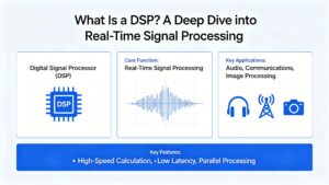
Learn how DSPs (Digital Signal Processors) enable real-time audio, industrial motor control, 5G communications & medical imaging. Compare DSP vs MCU, choose fixed vs floating-point DSPs, and source authentic DSP chips at ChipApex.
View details
The activity of extra discounts on wholesale prices is in full swing…
Please fill in your contact information and we will send you the latest wholesale price list.

