 ChipApex | Global Electronic Components Supplier

SEARCH
Search Product
Search Post
— IC芯片 | 连接器 | 传感器 | 被动器件 —
Search productSearch post
— IC芯片 | 连接器 | 传感器 | 被动器件 —
The trend of science and technology is changing rapidly.
A rectifier is a device or circuit that converts alternating current into current that flows in one direction. Its output is usually pulsating DC. Capacitors, regulators and other stages may then smooth and control that output. Choosing a rectifier means checking the circuit topology, voltage stress, current waveform, switching behavior and heat dissipation.
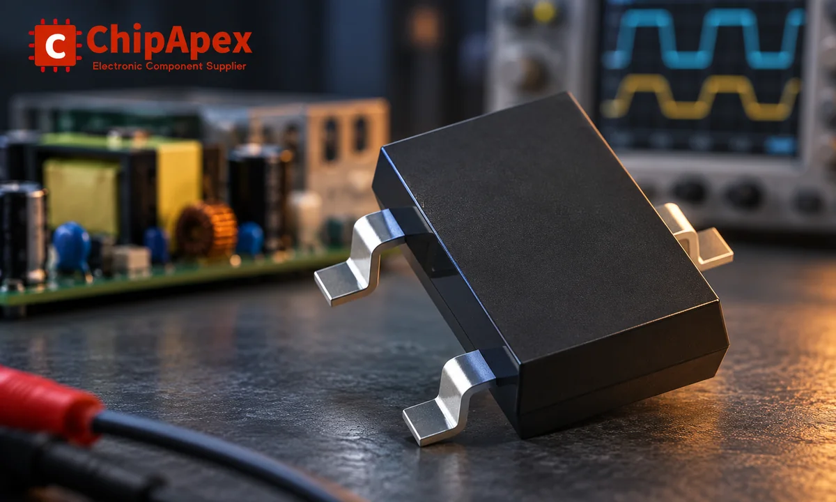
Rectification changes current direction; regulation controls the output voltage. A bridge and a reservoir capacitor can produce a DC bus, but that bus still varies with input voltage and load. A regulated supply adds a control stage to hold its output within a specified range.
The word also describes a component. A single rectifier diode may be one part of a bridge, a freewheeling path or a switching converter's output stage. ChipApex's rectifiers category is a useful starting point for component sourcing. The circuit around the part determines how its ratings must be interpreted.
For a low-voltage supply, a line-frequency transformer may reduce and isolate the AC before rectification. An offline switching supply commonly rectifies mains first and transfers energy across an isolation transformer later. A diode bridge alone provides no galvanic isolation.
For a single-phase sinusoidal input, the main differences are how many half-cycles reach the load and how the diodes connect to the source.
| Circuit | Diodes normally conducting at once | Transformer requirement | Main tradeoff |
|---|---|---|---|
| Half-wave | One | No center tap required | Simple, with long gaps between output pulses |
| Center-tapped full-wave | One | Center-tapped secondary | One forward drop in the conducting path, with different winding utilization and reverse-voltage stress |
| Single-phase full-wave bridge | Two | No center tap required | Uses both half-cycles, with two forward drops in the current path |
A half-wave circuit passes one half-cycle and blocks the other. With an ideal resistive load, its output pulses repeat at the AC input frequency. A full-wave circuit redirects both half-cycles through the load with the same polarity, so its ripple frequency is twice the input frequency. At 50 Hz, that means 100 Hz; at 60 Hz, 120 Hz.
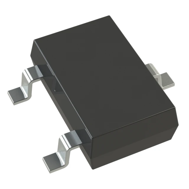
A center-tapped full-wave rectifier uses two diodes in total. A single-phase bridge uses four. Both are full-wave circuits. The manufacturer's bridge-rectifier definition confirms this distinction. When comparing an integrated bridge rectifier with separate diodes, also compare footprint, thermal path and pin arrangement.
Three-phase rectifiers form a separate design case. A conventional three-phase diode bridge has six diodes and six output pulses per AC cycle. Its input, commutation and filtering requirements should be evaluated for the actual three-phase system.
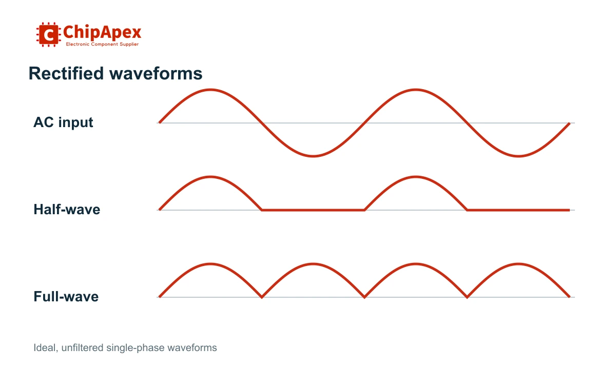
An ideal full-wave rectified sine has an average voltage of 2 × Vpeak / π, approximately 0.637 × Vpeak. That expression describes the unfiltered waveform. A capacitor-input supply behaves differently: the capacitor charges near the voltage peaks and supplies the load between charging pulses.
For a lightly loaded bridge with a reservoir capacitor, a first estimate of the peak capacitor voltage is:
Vcapacitor,peak ≈ √2 × VAC,RMS − 2 × VF
Here, VAC,RMS is the sinusoidal voltage applied to the bridge, and VF is the forward voltage of each conducting diode at the relevant current. Transformer regulation, source impedance, diode characteristics and load current change the result. This estimate is not a guarantee of the minimum DC voltage.
For example, an isolated 12 VAC secondary has an ideal peak of about 17 V. A bridge and capacitor therefore do not automatically deliver regulated 12 VDC. The available voltage falls during load discharge and changes with the AC input.
For small ripple and an approximately constant load current, a useful first estimate is:
ΔV ≈ Iload / (fripple × C)
At 0.20 A, 100 Hz ripple frequency and 2,200 µF, the estimate is about 0.91 V peak-to-peak. It excludes capacitor ESR, tolerance and charging-path losses. Select aluminum electrolytic capacitors by ripple-current capability and operating temperature as well as capacitance.
Increasing capacitance reduces discharge ripple, but it can raise charging peaks and startup stress. The bridge, transformer, fuse and inrush-limiting arrangement must tolerate those conditions together.
Standard silicon rectifiers suit many low-frequency applications. Fast and ultrafast types are intended for circuits where reverse recovery matters. Silicon Schottky diodes can reduce forward conduction loss, with tradeoffs in leakage and voltage capability. Silicon-carbide Schottky devices are often considered in higher-voltage switching stages.
A diode's reverse recovery occurs as stored charge is removed after forward conduction. The resulting current can add switching loss and excite ringing with circuit parasitics. Recovery specifications depend on test current, reverse voltage, current slew rate and temperature; two headline recovery-time values are not necessarily comparable.
The manufacturer's rectifier fundamentals reference identifies reverse voltage, average forward current, surge capability and recovery characteristics as selection parameters. Its terminology is useful when filtering the broader diode catalog.
At switching frequencies, the topology and commutation mode also matter. A component that works in a line-frequency bridge may be unsuitable for a hard-switched output rectifier. Conversely, the fastest device is not automatically the lowest-loss choice for a slowly commutated circuit.
| Datasheet item | What to establish before choosing a part |
|---|---|
| Repetitive peak reverse voltage, VRRM | Worst-case repeated reverse stress, including the relevant transients |
| Average forward current, IF(AV) | The specified waveform and mounting conditions behind the rating |
| Nonrepetitive surge current, IFSM | Pulse shape, duration, starting temperature and permitted repetition |
| Forward voltage, VF | Loss at the intended current and junction temperature |
| Reverse leakage, IR | Leakage at the intended blocking voltage and temperature |
| Recovery characteristics | Commutation conditions and the resulting switching loss or ringing |
| Thermal resistance and temperature limits | The actual board, copper area, enclosure and cooling path |
For a conducting single-phase bridge, a rough conduction-loss estimate is 2 × VF × Iload if forward drop is treated as constant. At 1 A and an assumed 0.8 V per diode, that gives about 1.6 W. A capacitor-input load has pulsed conduction, so use waveform-dependent calculations and thermal verification for the final design.
A package's current rating is conditional on its cooling. A small footprint does not establish the current it can carry in a sealed enclosure. Check junction temperature using the manufacturer's thermal model, then verify it in representative hardware.
Surge current deserves separate attention. A single half-sine surge rating does not authorize repeated high-current charging pulses. Likewise, connecting diodes in parallel does not establish equal current sharing, and connecting them in series does not establish equal blocking-voltage sharing.
Excessive ripple can come from insufficient capacitance, an aged capacitor, excessive load or a failed rectifier path. Losing one path in a full-wave circuit can reduce the charging frequency and increase ripple. Measurements should distinguish the AC input, rectifier output and regulated output.
Overheating may indicate excessive RMS current, poor cooling, high forward loss or reverse-recovery stress. Startup failures often require an inrush investigation rather than a larger steady-state current rating. Ringing calls for a review of layout, commutation loops and any required suppression network.
For a finished industrial ac to dc converter, check the complete module specification. Its isolation, regulation and protection behavior cannot be inferred from the rectifier alone.
A diode is a component with asymmetric conduction. Rectification is a function. A single diode can provide half-wave rectification, while a bridge uses several diodes. Some rectifier circuits use controlled semiconductor switches. The terms overlap in component catalogs, but the circuit function and device specification still need to be distinguished.
Its raw output is pulsating DC. A reservoir capacitor reduces the variation between voltage peaks, and a regulator may control the final voltage. The required filtering depends on load current, allowed ripple and input frequency. The bridge itself does not establish a fixed output voltage.
A bridge generally provides more frequent charging pulses and better use of the input waveform. It also adds a second forward drop in the conducting path. A simple half-wave arrangement can still suit some low-power functions. Choose from the complete load and source requirements rather than a universal ranking.
An ordinary diode rectifier does not perform that function. An inverter generates AC from DC using controlled switching. Some actively controlled power converters support power flow in both directions, but that capability requires an appropriate topology, control system and specification. A passive bridge does not provide it.
Provide the exact part number if available, circuit role, input voltage range, average and peak current, switching frequency, package and expected temperature. Include quantity and any qualification requirements. For a replacement, compare recovery behavior and thermal conditions as well as the printed voltage and current ratings.
For a ChipApex sourcing request, send the preferred part number or the operating conditions above, together with the required quantity. That gives the component review a defined electrical and mechanical target.
Learn what an integrated circuit is, how ICs work, the main types and the specs to check before choosing a part for your design with ChipApex.
View details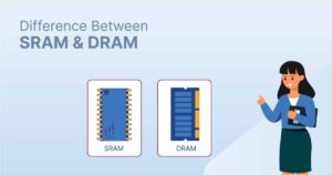
Discover why SRAM remains essential in industrial, medical & aerospace systems—thanks to its deterministic performance and long-term reliability. Trusted by engineers worldwide.
View details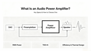
Learn what an audio power amplifier is, the differences between Class D and AB, and how to choose the right IC. Includes PCB layout tips and part recommendations. Shop at ChipApex.
View details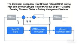
Ground potential shift during high dI/dt regen braking causes isolated CAN receivers to output false dominant states, locking EV BMS networks. Discover robust solutions like TJA1044GT/3Z + common-mode filtering validated by ChipApex.
View details
The activity of extra discounts on wholesale prices is in full swing…
Please fill in your contact information and we will send you the latest wholesale price list.

