 ChipApex | Global Electronic Components Supplier

SEARCH
Search Product
Search Post
— IC芯片 | 连接器 | 传感器 | 被动器件 —
Search productSearch post
— IC芯片 | 连接器 | 传感器 | 被动器件 —
The trend of science and technology is changing rapidly.
An RTD, or resistance temperature detector, measures temperature through a sensing element’s predictable resistance change. Selecting an RTD system requires the element type, resistance curve, wiring, excitation and mechanical installation to be considered together. Pt100 or Pt1000 identifies nominal resistance, while the complete measurement chain determines the temperature error at the point of use.
A bare element, a finished probe and a transmitter with a digital or current-loop output are different products. The element produces a resistance change. Electronics convert that change into a temperature value, and the mounting arrangement determines how closely the element follows the intended target temperature.
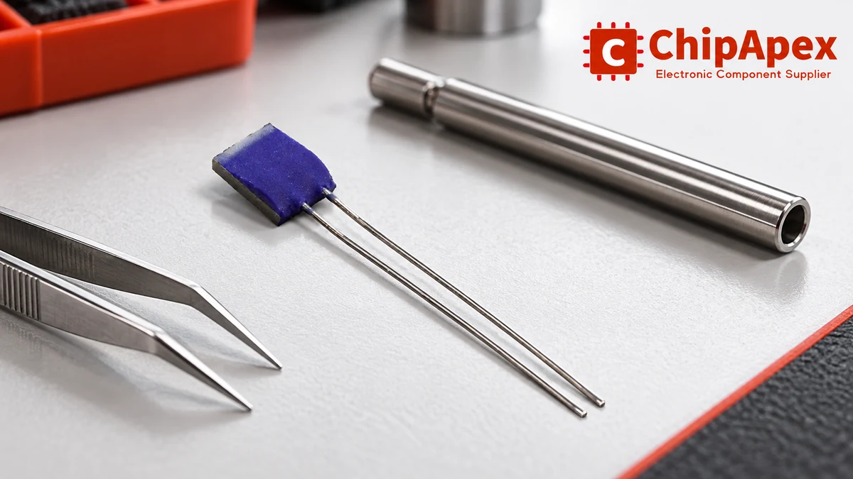
Platinum RTDs are common in temperature measurement. A Pt100 has a nominal resistance of 100 Ω at 0°C; a Pt1000 has a nominal resistance of 1,000 Ω at 0°C. Those names do not establish the full resistance curve, element tolerance, usable temperature range or mechanical construction.
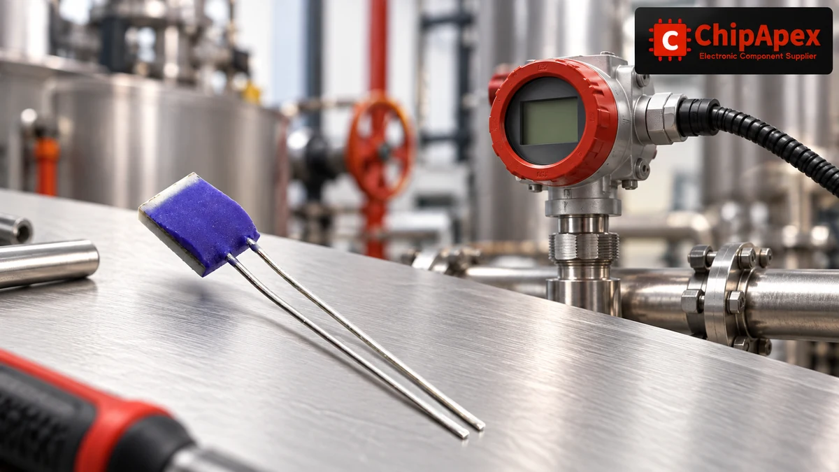
When comparing rtd temperature sensors, request the resistance characteristic and applicable tolerance specification for the exact part. Thin-film and wire-wound constructions can bring different mechanical and application considerations. A probe’s cable, sheath and termination can limit its usable range even where the element itself supports a wider range.
RTD resistance is approximately linear over limited temperature intervals. Accurate conversion across a wider interval needs the specified resistance-temperature relationship, often expressed through a Callendar-Van Dusen equation for platinum elements. A single straight-line slope is useful for local estimates; it is not a substitute for the appropriate conversion curve.
The manufacturer’s guide to RTD measurements explains sensing characteristics and measurement circuits. Use its circuit assumptions with the selected element and converter rather than copying a conversion equation without checking the applicable coefficients and range.
A Pt1000 provides a larger resistance change per degree than a Pt100 with the same normalized resistance characteristic. For a given amount of added lead resistance, that can reduce the corresponding temperature error. The instrument must support the selected element and its resistance range.
| Selection factor | Pt100 | Pt1000 |
|---|---|---|
| Nominal resistance at 0°C | 100 Ω | 1,000 Ω |
| Added lead resistance | Larger relative contribution for the same added resistance | Smaller relative contribution for the same added resistance |
| Excitation design | Check required signal and self-heating together | Can support lower excitation for a chosen signal target, subject to the circuit |
| Instrument compatibility | Must be explicitly supported | Must be explicitly supported; do not assume a Pt100 input can accept it |
| Accuracy and response | Depend on construction, tolerance, installation and electronics | Depend on construction, tolerance, installation and electronics |
Pt1000 does not automatically mean better complete-system accuracy or lower self-heating. At the same current, its larger resistance dissipates more power. A designer can instead choose a lower current, while still obtaining a useful voltage signal. Compare the actual excitation and thermal conditions.
If the application is still choosing among temperature sensors, settle the required temperature range, response, installation and interface first. An RTD wiring decision comes after confirming that resistance measurement is appropriate for the target and environment.
Two-wire measurement includes the resistance of both connecting leads in the measured path. That contribution changes with wire length, cross-section, connections and temperature. It can dominate a low-resistance sensor measurement even when the element tolerance is good.
Three-wire arrangements add a connection that lets an appropriate circuit compensate for lead resistance. The result depends on the measurement architecture and assumptions about lead matching and excitation. It does not remove every error from every three-wire installation.
Four-wire measurement separates current-carrying and voltage-sensing connections. With a suitable instrument and low sense-input current, voltage drop along the current leads contributes much less to the sensed element voltage. Contact quality, leakage, compliance and other circuit errors still need attention.
| Connection | Main advantage | Conditions to review |
|---|---|---|
| Two-wire | Fewer conductors and a simple connection | Combined lead resistance and its temperature change |
| Three-wire | Lead compensation with less wiring than four-wire | Lead matching and the converter’s specific compensation method |
| Four-wire | Separate force and sense paths | Correct terminal connections, input behavior and excitation compliance |
The connection guide for Pt100 sensors describes these arrangements. Confirm the manufacturer’s terminal diagram instead of relying on cable color alone. Color conventions and connector assignments can vary.
Consider an illustrative local estimate near 0°C. Suppose a two-wire connection adds 1 Ω in total from both leads and connections. Using rounded local sensitivities of about 0.391 Ω/°C for a Pt100 and 3.91 Ω/°C for a Pt1000, the corresponding uncompensated errors are approximately 2.6°C and 0.26°C.
This comparison uses the same added resistance and a local linear approximation. It does not describe a complete calibration or guarantee error elsewhere in the temperature range. Use the specified conversion relationship when calculating temperature from resistance.
If the cable temperature changes, a correction recorded at one installation condition may no longer represent the current lead resistance. A three-wire design should examine the residual mismatch between the paths its compensation method uses. A four-wire design still needs an instrument that can maintain the intended excitation and sense correctly over the installed cable.
Write the allowed lead-related contribution into the error budget. That makes the wiring choice an engineering decision tied to the required uncertainty, rather than an assumption that more wires always solve every problem.
An RTD measurement circuit applies excitation and measures the resulting voltage. The element dissipates power approximately according to P = I²R. Some of that power raises the element above the surrounding target temperature, depending on its thermal coupling and environment.
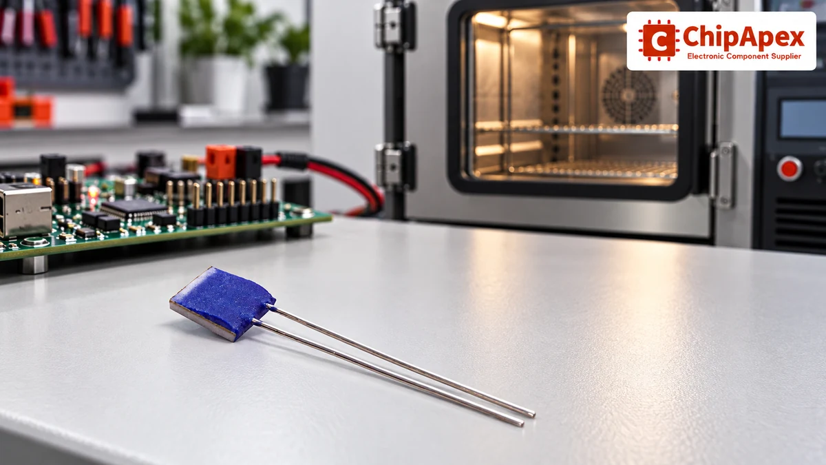
For a simple illustration at 0°C, 1 mA through a 100 Ω element dissipates 0.1 mW. The same 1 mA through a 1,000 Ω element dissipates 1 mW. These are electrical power calculations, not temperature-rise predictions. A temperature rise needs the relevant dissipation or thermal information for the actual installation.
Reducing current reduces self-heating but also reduces signal voltage. Review the converter’s noise, gain, settling and reference arrangement before choosing excitation. Pulsed excitation may be useful in a particular design, but requires adequate settling and an application-specific timing review.
For small signals, instrumentation amps may be part of the measurement chain. Their offset, drift, input range and bias behavior need to fit the sensor circuit. Adding gain cannot correct a probe that is measuring the wrong physical temperature.
List the contributions separately: element tolerance, resistance-curve or conversion error, lead effects, excitation and reference behavior, electronics offset and drift, noise, and thermal installation. Keep units and assumptions consistent before combining them.
Some errors are systematic and can share dependencies. Others are noise or uncertainty components assessed through a defined method. Do not add incompatible accuracy figures or assume that every contribution is independent just to obtain a smaller total.
An integrated analog front end can combine useful measurement functions. Check what is included and which conditions its accuracy specification covers. The resolution of an adc converter describes its digital code structure; it does not establish temperature accuracy after reference error, input noise, sensor tolerance and installation effects.
Finally, review the conversion and fault handling in the microcontrollers or instrument that reports the value. Firmware needs the correct element characteristic, coefficients, units and calibration data. It should distinguish a plausible temperature from an open lead, shorted element or other invalid input where the hardware supports that diagnosis.
The element measures its own temperature. A surface installation needs adequate thermal contact with the target and a review of heat carried through leads or mounting hardware. A probe in a process needs suitable insertion, contact and response for that installation.
A thick sheath, protective potting or thermowell can change response time. Radiation, airflow and nearby heat sources can also affect the reading. A probe beside a hot power component may give a repeatable result that does not represent the temperature the controller is meant to regulate.
Specify the range for the entire assembly, including leads, insulation, connector, adhesive and sheath where present. Include mechanical stresses, chemical exposure and vibration. A category photograph of a bare RTD element does not verify the performance of an assembled industrial probe.
Their nominal resistances at 0°C are 100 Ω and 1,000 Ω respectively. With the same normalized characteristic, a Pt1000 gives a larger resistance change per degree, making the same added lead resistance a smaller temperature-error contribution. Complete accuracy, range and response still depend on the element, electronics and installation. Confirm that the instrument supports the chosen type.
It can compensate for lead resistance through a suitable measurement method, but its residual error depends on that method and assumptions such as lead matching. Unequal wires, contacts or temperatures can leave a contribution. Use the converter’s circuit guidance and evaluate the installed cable. Three conductors alone do not prove that compensation is operating correctly.
Four-wire measurement separates excitation current from voltage sensing. A suitable instrument can then sense the element voltage with much less contribution from the current-carrying leads. Check terminal assignment, sense-input behavior and excitation compliance. The method reduces an important electrical error source, while element tolerance, thermal contact and the rest of the electronics remain part of the measurement budget.
No. At the same excitation current, the larger resistance dissipates more power because power equals current squared times resistance. A Pt1000 design can use a lower current for a chosen signal requirement, which may reduce heating. Compare the actual current and the element’s thermal environment before drawing a conclusion about temperature rise.
An RTD needs an appropriate excitation and resistance-measurement circuit. Some controllers or associated converters provide relevant functions, while others require an external analog front end. Review input range, reference, noise, lead compensation and fault behavior. Connecting a resistance element to an arbitrary digital pin does not produce a defined temperature measurement.
Sensor tolerance covers the element or assembly under its specified conditions. The reported temperature also depends on wiring, excitation, reference, conversion, noise and thermal installation. Keep those contributions separate in an error budget. A low-tolerance element can still report the wrong target temperature when mounted poorly or used with an unsuitable measurement circuit.
For a ChipApex sourcing request, provide Pt100/Pt1000 or the exact element specification, resistance characteristic, tolerance requirements, wiring arrangement and operating range. Add mechanical drawings, lead and connector requirements, excitation conditions, quantity and any required documentation. Ask for the full part datasheet before approving a substitute.
Learn what an integrated circuit is, how ICs work, the main types and the specs to check before choosing a part for your design with ChipApex.
View details
Stop guessing which Op-Amp to use. We break down GBWP, Slew Rate, and Offset Voltage with real engineering insights. Find the right parts like NE5532DR & LM358DR at ChipApex.
View details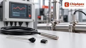
Compare thermistors, RTDs, thermocouples and temperature ICs. Learn how range, accuracy, response, interfaces and mounting affect component selection.
View details
Learn the relay definition, coil and contact operation, NO and NC forms, load ratings and suppression choices. Compare mechanical, reed and solid-state types.
View details
The activity of extra discounts on wholesale prices is in full swing…
Please fill in your contact information and we will send you the latest wholesale price list.

