 ChipApex | Global Electronic Components Supplier

SEARCH
Search Product
Search Post
— IC芯片 | 连接器 | 传感器 | 被动器件 —
Search productSearch post
— IC芯片 | 连接器 | 传感器 | 被动器件 —
The trend of science and technology is changing rapidly.
A relay is an electrically operated switch that lets a control circuit change another circuit's state. An electromechanical relay moves contacts using a magnetic coil. A solid-state relay uses semiconductor devices. Selection depends on the control input, contact or output behavior, load type, insulation requirements and expected operating life.
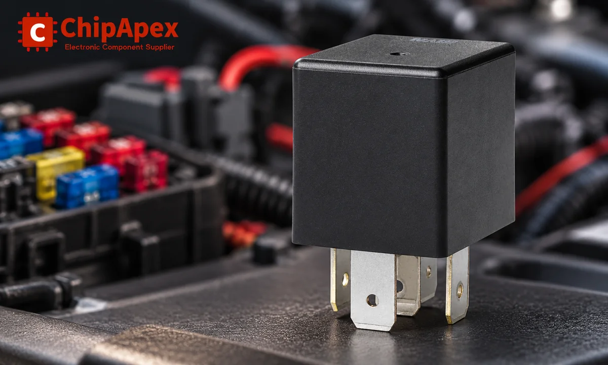
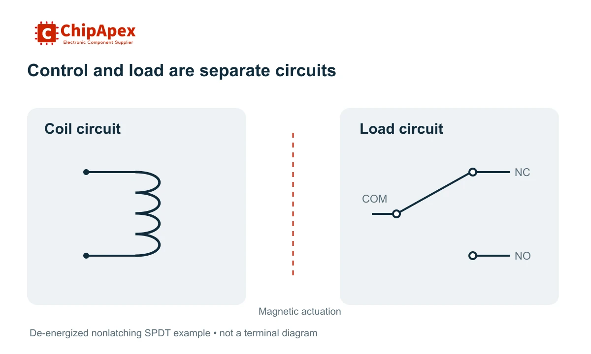
In an electromechanical relay, current through a coil creates a magnetic field that moves an armature. That movement opens or closes contacts in the load circuit. The controller supplies the command, while a separate source normally supplies the load's operating energy.
This arrangement lets a modest control signal operate a different voltage or current. It does not mean every relay can switch any load. The coil rating, contact rating and insulation specification are separate constraints.
ChipApex lists relays across several product families. Begin with the type of load and required contact behavior, then narrow the choice by control voltage and mechanical format. An identical housing does not establish an identical circuit.
The physical separation between coil and contacts can provide galvanic isolation, but suitability for safety insulation requires the exact device ratings and installation conditions. A relay on a module with closely spaced PCB tracks does not automatically give the assembled board the same insulation performance.
For a conventional nonlatching relay, normally open and normally closed describe the contacts with the coil de-energized. Energizing the coil changes their state. A latching relay retains a state after its operating pulse, so its reset and set conditions need separate attention.
| Term | Meaning |
|---|---|
| NO | Normally open contact; open in the defined normal state |
| NC | Normally closed contact; closed in the defined normal state |
| COM | Common terminal in a changeover arrangement |
| Form A | Normally open contact arrangement |
| Form B | Normally closed contact arrangement |
| Form C | Changeover arrangement connecting COM to one of two contacts |
| SPST / SPDT | One pole with one throw / one pole with two throws |
| DPDT | Two poles, each with two throws |
Check the manufacturer's wiring diagram for terminal numbers and the stated viewing direction. A bottom view and a top view can appear mirrored. Automotive terminal conventions also do not establish the pinout of every relay family.
| Type | Useful characteristics | Limits to check |
|---|---|---|
| Electromechanical | Multiple contact forms and a physical contact gap | Contact wear, bounce, operating time and coil power |
| Reed | Sealed magnetic contacts useful in many signal-switching duties | Permitted load, inrush, magnetic environment and hot-switching life |
| Latching | State can be retained without continuous coil energization | Pulse requirements, set/reset method and behavior after loss of control power |
| Solid-state | No moving contact mechanism and potentially frequent operation | On-state loss, heat removal, off-state leakage and output compatibility |
A reed relay can fit a low-level signal path where leakage, contact resistance and isolation matter. It still needs protection from load conditions outside its switching rating. A power relay with a large current rating may perform poorly at extremely small signals if its contact system is unsuitable for microloads.
For solid state relays, check whether the output is intended for AC, DC or a specified bidirectional use. A triac-based AC output is not a general substitute for a DC switch. Zero-cross and random-turn-on behavior also serve different load-control needs.
The manufacturer's relay technology comparison explains how switching speed, resistance, life and output characteristics differ among technologies.
A 12 VDC coil tells you how the relay is actuated. It does not state the maximum voltage or current the contacts can switch. Similarly, a contact rating printed for AC does not authorize the same current at an arbitrary DC voltage.
For the coil, check nominal voltage, allowed voltage range, current or power, pickup conditions, release conditions and temperature effects. Use the specified AC frequency where applicable. An undervoltage coil can fail to pull in reliably, while excessive voltage can overheat it.
As a calculated example, a DC coil drawing 30 mA at 12 V consumes 0.36 W. Whether a controller can drive it directly depends on that controller's output specification and the required suppression. A transistor, MOSFET or relay driver is often used between logic and coil.
For the contacts, check switching voltage, switching current, maximum switching power and the permitted load category. These are an operating envelope. Separate maximum values should not be combined into a new operating point unless the datasheet permits it.
When browsing 12v relays, also establish whether 12 V refers to the coil, the vehicle application or a specific contact-load rating. The complete part number and wiring diagram resolve that ambiguity.
Resistive loads, motors, lamps and capacitive inputs stress contacts differently. Motor startup and capacitor charging can produce inrush above normal running current. Inductive loads can sustain an arc during opening. A relay rated for a resistive load therefore needs a separate assessment for these duties.
AC current periodically crosses zero, which can help extinguish an arc. DC lacks that natural zero crossing, so DC switching capability can be much lower under otherwise similar conditions. Use the manufacturer's DC load curve or specified rating.
Mechanical life counts operations under stated mechanical test conditions. Electrical life includes switching a specified load. A large mechanical-life figure cannot predict loaded service life on its own. Switching frequency, temperature, contamination and suppression also affect the result.
The manufacturer's relay application guidance covers load ratings, inrush and minimum-load contact behavior. Verify performance under the intended equipment conditions when the load falls outside a directly specified case.
When a DC coil turns off, its stored magnetic energy can create a voltage transient. A suppression network limits the stress on the driver and helps control emissions. A simple flyback diode is common, but it can slow current decay and relay release.
Slower release can change the way contacts interrupt a load. A diode plus a suitable voltage clamp or a driver with a specified clamp may give different behavior. The choice must fit the relay manufacturer's guidance and the driver's permitted voltage and energy.
The manufacturer's coil-suppression white paper describes this tradeoff. Do not apply a DC flyback-diode arrangement blindly to an AC coil.
Protecting the switched load path is another task. An inductive load may need its own suppression, selected for the load, required release behavior and contact rating. A diode across the relay coil does not suppress every transient generated by the load circuit.
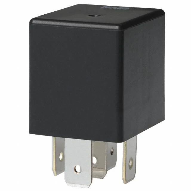
Board-mounted and socket-mounted relays have different service and assembly requirements. Match relay sockets to the relay series, terminal arrangement, current capability and retention requirements. A socket and a relay each have ratings; the assembly is limited by their combined installation conditions.
Chattering can indicate a collapsing coil supply, incorrect drive or excessive ripple. A clicking sound confirms movement, but it does not prove the load contacts have low resistance or the wiring is correct. Welded contacts can remain closed after the coil is de-energized.
For an SSR, a small off-state current may be normal, and on-state dissipation can require a heatsink. A zero-current measurement or a continuity beeper cannot fully characterize every SSR output. Use the manufacturer's test method and check the circuit under appropriate load conditions.
A relay performs a switching function using an electrical control input. A manual switch is operated directly by a person or mechanism. Both must be selected for the circuit they control. Relays are useful when the command location, control current or circuit isolation makes direct manual switching unsuitable.
It commonly describes a relay with a nominal 12 V coil, but listings can also refer to an automotive application. Confirm the complete coil specification and contact ratings separately. A 12 V coil does not establish the load current, DC interrupting capacity or terminal arrangement.
Only if its output specifications cover the coil's voltage, current and inductive turn-off conditions. Many applications need a transistor, MOSFET or driver plus appropriate suppression. Check startup states as well: an uncontrolled output during reset can unintentionally energize the relay even if the steady-state software is correct.
An SSR can suit frequent operation or applications requiring quiet switching. It also has on-state losses and off-state leakage, and its output must match the load. An electromechanical relay may suit other requirements better. Compare the actual load, switching frequency, heat removal and required off-state behavior.
The coil may move the armature while worn contacts, incorrect terminal wiring or a damaged socket prevent load current. The load supply or load itself may also be faulty. Test the control and load paths separately using the circuit diagram; sound alone cannot confirm electrical continuity or contact condition.
For a ChipApex relay inquiry, send the coil voltage, contact form, load voltage and current, load type, switching frequency, mounting format and quantity. Include the existing part number and socket details for a replacement.
Compare RC, crystal and MEMS oscillator circuits. Check ppm, jitter, load capacitance, startup margin and output compatibility before choosing a clock source.
View details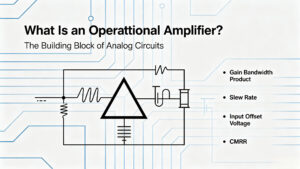
Stop guessing which Op-Amp to use. We break down GBWP, Slew Rate, and Offset Voltage with real engineering insights. Find the right parts like NE5532DR & LM358DR at ChipApex.
View details
A positive temperature coefficient (PTC) thermistor is a resistor whose resistance rises as its temperature rises. Depending on its material and curve, that change can be gradual or very steep around a transition temperature. Designers use PTC par...
View details
What is EEPROM? Learn byte-level storage, EEPROM vs Flash, I2C/SPI, BOM selection & sourcing risks. Authentic EEPROMs at ChipApex.
View details
The activity of extra discounts on wholesale prices is in full swing…
Please fill in your contact information and we will send you the latest wholesale price list.

