 ChipApex | Global Electronic Components Supplier

SEARCH
Search Product
Search Post
— IC芯片 | 连接器 | 传感器 | 被动器件 —
Search productSearch post
— IC芯片 | 连接器 | 传感器 | 被动器件 —
The trend of science and technology is changing rapidly.
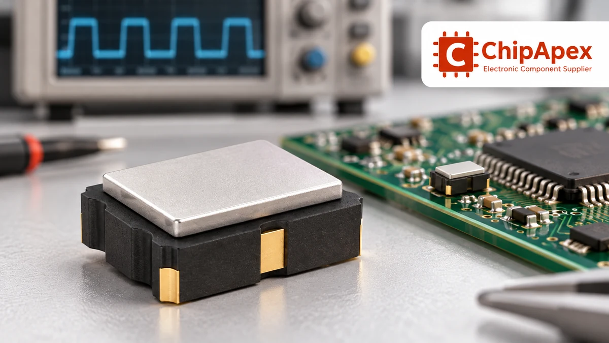
An oscillator produces a repeating electrical waveform without a repeating external input. In electronic timing, RC circuits, crystal-based circuits and packaged MEMS oscillators provide different balances of accuracy, power, startup behavior and integration effort. Choose the clock source from the receiving device’s timing requirements, then check its electrical interface and operating conditions.
A bare quartz crystal and a powered oscillator module perform different roles. A crystal is a resonator that needs a sustaining circuit. An oscillator module contains the circuitry needed to deliver a clock output. Substituting one for the other usually requires changes to the connection and configuration of the receiving device.
A resonant or timing element establishes a preferred frequency. An active circuit supplies energy and maintains the oscillation. The resulting waveform may then pass through buffers, dividers or a PLL before reaching the circuits that use it.
For a microcontroller, first identify the permitted clock modes: internal RC, external crystal or resonator, and external clock input. Pin names alone can be misleading. The same pin may have different behavior depending on configuration bits or software settings.
For a ready-made clock source, compare oscillators by the required output interface, supply, frequency and stability. For a crystal-connected MCU, select the resonator and load network against the MCU’s oscillator recommendations instead.
| Clock-source approach | What establishes timing | Reasons to consider it | Checks that remain essential |
|---|---|---|---|
| Internal RC | Integrated resistance/capacitance behavior and control circuitry | Low component count and convenient integration | Accuracy over supply and temperature; calibration and protocol requirements |
| External RC circuit | Resistors, capacitors and active circuitry | Adjustable timing and simple noncritical functions | Component tolerance, drift, waveform and loading |
| Bare crystal with sustaining circuit | Quartz resonance with an active oscillator stage | Established frequency reference for compatible ICs | Load capacitance, ESR, drive level, startup margin and layout |
| Packaged quartz oscillator | Crystal and sustaining circuitry inside a module | Specified clock output and reduced resonator-matching work | Supply, output standard, jitter, stability and enable behavior |
| Packaged MEMS oscillator | MEMS resonator with electronic sustaining and conditioning circuitry | Integrated timing option with configurable product variants | Exact frequency, interface, jitter, power and environmental specifications |
Quartz and MEMS are technologies, not quality grades. A general-purpose module in either family can be unsuitable for a demanding interface. Compare equivalent operating conditions and complete specifications instead of assuming one technology always has lower jitter or better accuracy.
An RC source can suit control tasks where the timing tolerance is loose enough for the application. Examples include basic timeout functions and processing that does not require an independent precision time reference. An internal RC source can also reduce external components and simplify startup architecture.
Check its guaranteed error across the actual supply and temperature range. A factory-trimmed room-temperature figure is different from a full-range maximum. Some devices support user calibration or automatic adjustment against another reference; that reference, its availability and the calibration procedure become part of the design.
Communication interfaces, sampling systems and real-time clocks impose their own timing limits. Confirm the receiving protocol’s clock-error budget and the MCU’s implementation before deciding an RC source is adequate. Avoid carrying an accuracy number from one microcontroller family into another.
In an external RC timing circuit, resistor and capacitor tolerances combine with active-device thresholds and temperature effects. The familiar relationship between frequency and RC depends on the oscillator topology. Use that topology’s equation and limits rather than a universal f = 1/RC assumption.
Electronic crystals are specified for a particular mode, load condition and drive level. Match nominal frequency, frequency tolerance, load capacitance, maximum ESR, shunt capacitance and allowed drive to the sustaining circuit.
For a simple two-capacitor Pierce arrangement, a common first estimate is C load ≈ (C1 × C2) ÷ (C1 + C2) + C stray. The stray term includes relevant pin and PCB effects. Equal external capacitors do not each equal the crystal’s stated load capacitance.
For an illustrative 12 pF target load and an assumed 3 pF total stray contribution, equal capacitors would initially calculate to 18 pF each. This is a starting estimate, not a recommended value for every MCU. The actual circuit and layout must be evaluated.
ESR and sustaining-amplifier capability affect whether oscillation starts reliably. A circuit that runs on a warm bench can fail at a cold start or a different supply voltage if the startup margin is inadequate. Validate the manufacturer-recommended margin method rather than treating a visible waveform as proof of robustness.
Excessive crystal drive can shift frequency or damage the resonator. Reducing drive indiscriminately can also harm startup. Use the IC and crystal manufacturers’ methods for determining drive level, external resistance and startup margin. The oscillator design application note provides a detailed treatment of these related checks.
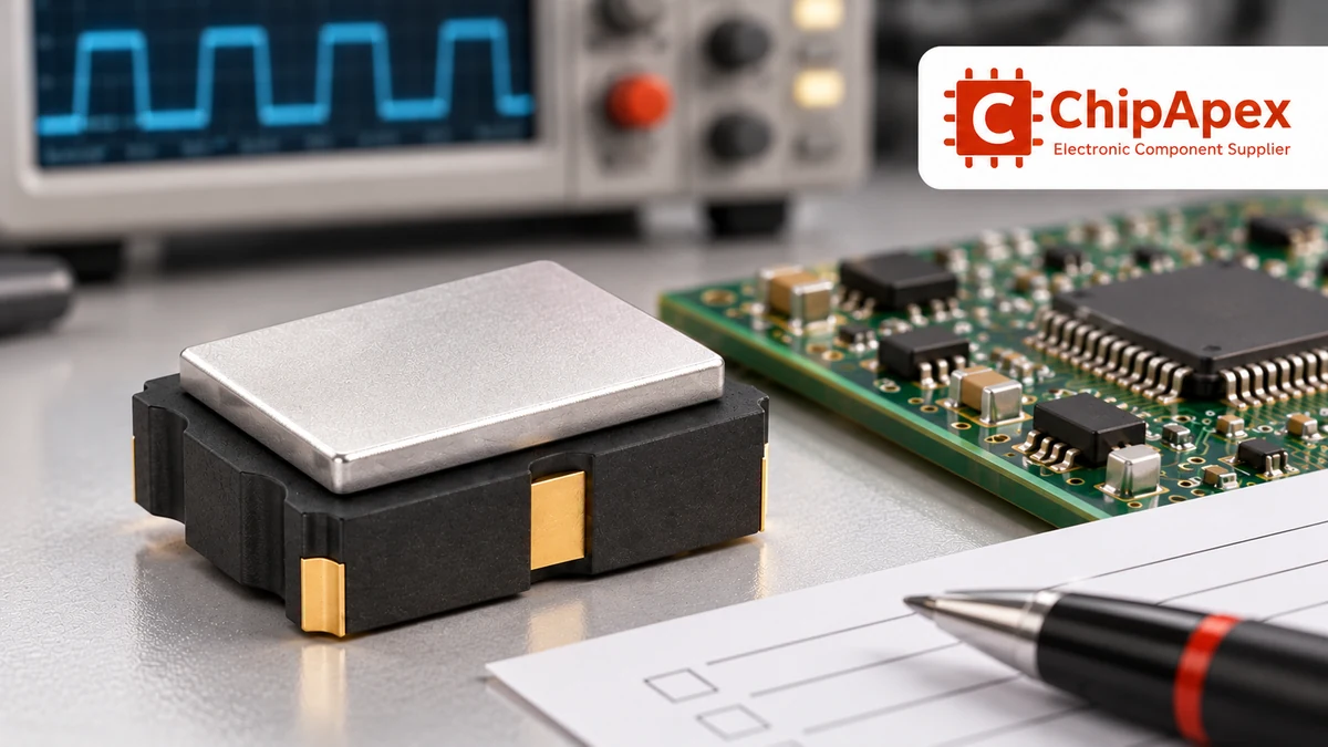
Parts per million express a fractional frequency error: error in hertz = nominal frequency × ppm ÷ 1,000,000. At 20 MHz, 20 ppm corresponds to 400 Hz. A constant 20 ppm timebase error would accumulate about 1.728 seconds over 24 hours.
Those calculations describe the stated error, not necessarily the entire clock budget. Datasheets may distinguish initial frequency tolerance, temperature stability, aging, supply sensitivity and load sensitivity. Some module stability specifications combine several terms; others list them separately. Read the definition before adding figures or comparing products.
Consider whether the receiving system needs absolute frequency accuracy, matching between clock domains or short-term edge stability. A clock can have accurate average frequency while its individual edges exhibit more jitter than the interface allows.
Temperature-compensated and oven-controlled oscillators address particular stability requirements. Their power, warm-up behavior and environmental limits differ from simple oscillator modules. Choose them when the system budget needs those features, rather than treating a tighter headline figure as a free upgrade.
Jitter describes timing variation of signal edges. Period jitter, cycle-to-cycle jitter, time interval error and integrated phase jitter are different measurements. An RMS phase-jitter figure cannot be compared directly with a peak-to-peak period-jitter figure as though they were the same quantity.
For phase jitter, check the integration offset-frequency band. For time-domain measurements, check observation length, sample count and measurement bandwidth. Also compare supply, output loading, nominal frequency and temperature conditions.
The clock jitter measurement reference explains these distinctions. In a procurement comparison, carry the required definition and measurement conditions into the specification so proposed alternates can be evaluated consistently.
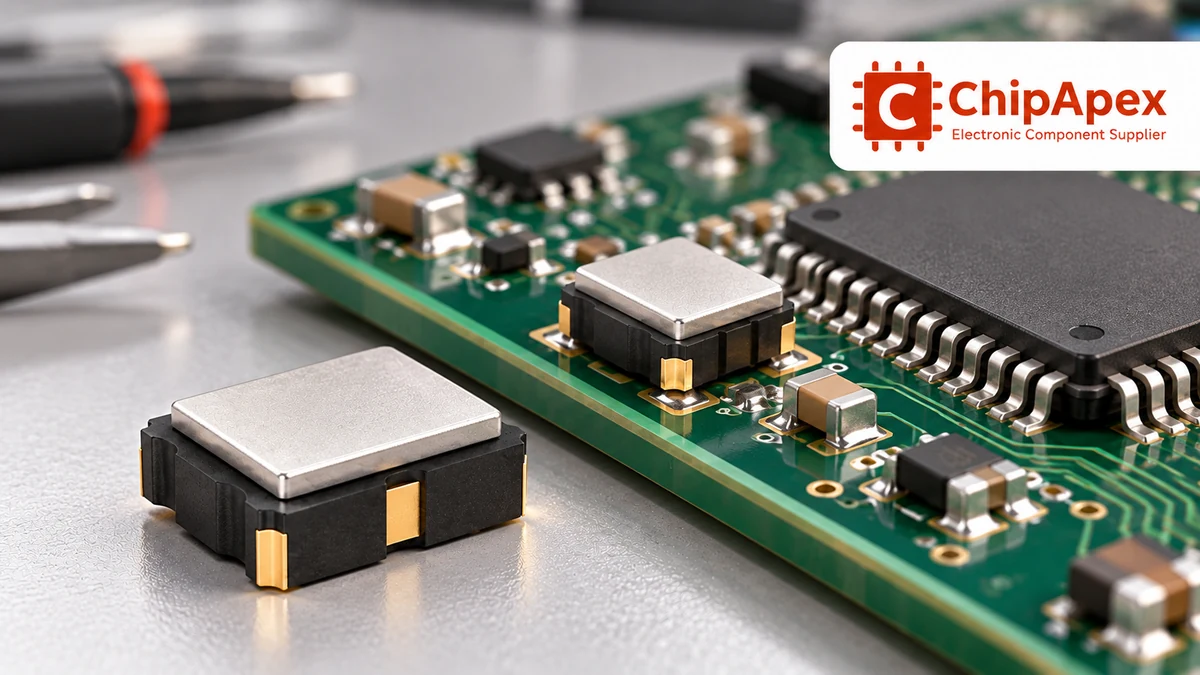
LVCMOS, LVDS, LVPECL and HCSL outputs have different electrical requirements. Package size and nominal frequency do not establish compatibility. Check output swing, common-mode behavior, termination and the receiving device’s permitted input arrangement.
For a CMOS clock, verify input thresholds, supply relationship, capacitive load and edge-rate requirements. Driving several loads may require a clock buffer. A long trace or branch can introduce reflections and timing uncertainty even when the oscillator itself meets its datasheet.
Check enable, standby and output-disable behavior. A disabled output can be low, high-impedance or otherwise defined by the device. Its startup and enable times can matter when the system wakes from sleep. Confirm pinout and pin-1 orientation against the exact mechanical drawing.
If the BOM uses programmable parts, verify whether “programmable” means factory-configured, one-time-programmed or adjustable in the end system. Orderable frequency codes and configuration services vary by product. A generic frequency range on a family page does not establish the setting of the quoted part.
Keep the crystal loop compact and away from noisy switching paths. Follow the IC manufacturer’s grounding and keepout guidance for that specific oscillator block. Avoid copying a guard-ring arrangement without checking the associated ground and layer assumptions.
A packaged module also needs suitable decoupling, a controlled return path and sensible clock routing. Supply noise can modulate the output timing. Confirm whether extra filtering is necessary, and account for any voltage drop it introduces.
Measurement probes add capacitance and can disturb a sensitive crystal circuit. Use the recommended probe method and, where possible, measure a buffered clock output instead. A stopped or shifted oscillator after attaching a probe can be a measurement artifact.
Validate startup across supply ramp, temperature and repeated power cycles. For an alternate component, repeat the important checks in the actual board rather than relying on frequency and footprint matching alone.
A bare crystal is a passive resonator. It requires a suitable active circuit to sustain oscillation. A packaged crystal oscillator includes that circuitry and delivers a clock output when powered. Check whether the receiving IC expects a crystal connection or an external clock before choosing either part.
No. Accuracy, stability and jitter depend on the specific product and its operating conditions. Compare the full specification for the application, including temperature range, aging, output standard and measurement definitions. Broad technology claims are insufficient for approving one part as an equivalent replacement.
Possible causes include an unsuitable ESR, excessive loading, insufficient sustaining gain, incorrect clock-mode configuration or PCB coupling. Supply ramp and temperature can expose marginal designs. Check the MCU and crystal requirements together, then measure startup margin and drive using the recommended method.
It means a fractional frequency error of 20 parts per million under the specified conditions. At 20 MHz, that is 400 Hz. If a constant 20 ppm error persisted for a day, the time error would be approximately 1.728 seconds. Other error terms may need inclusion in the complete budget.
Only after checking the full pinout, supply range, output standard, load requirements, frequency specification, startup and control-pin behavior. A mechanically matching part can drive an incompatible voltage or termination. Review environmental and lifecycle requirements as well as the board-level electrical interface.
Use the same jitter definition and measurement conditions. Check RMS versus peak-to-peak, the phase-jitter integration band, measurement bandwidth and output loading. If the vendor data use different methods, request comparable information instead of ranking the values directly.
Send ChipApex the full part number or required clock frequency, stability definition, jitter limit and measurement band, output interface, supply, package and temperature range. Include control-pin requirements and quantity. Request the exact frequency configuration and datasheet with any proposed alternative.

What is EEPROM? Learn byte-level storage, EEPROM vs Flash, I2C/SPI, BOM selection & sourcing risks. Authentic EEPROMs at ChipApex.
View details
Understand thermal fuse operation, Tf, Th and Tm, electrical ratings and mounting. Check temperature limits and replacement requirements for your design.
View details
Learn how rectifiers convert AC to DC, compare half-wave and bridge circuits, and select voltage, current, recovery and thermal ratings for your design.
View details
Discover how NOR flash enables fast code execution in embedded systems, its key types (Parallel/SPI), and how to source authentic, traceable ICs from trusted suppliers.
View details
The activity of extra discounts on wholesale prices is in full swing…
Please fill in your contact information and we will send you the latest wholesale price list.

