 ChipApex | Global Electronic Components Supplier

SEARCH
Search Product
Search Post
— IC芯片 | 连接器 | 传感器 | 被动器件 —
Search productSearch post
— IC芯片 | 连接器 | 传感器 | 被动器件 —
The trend of science and technology is changing rapidly.
Select a power transformer by matching the input voltage and frequency, required secondary voltages, RMS load currents, insulation requirements and thermal conditions. Then check regulation, startup behavior and mechanical fit. For a rectified DC supply, calculate the transformer loading from the rectifier and filter arrangement rather than equating DC output watts with transformer VA.
This guide addresses power transformers used in equipment, controls and electronic assemblies. Utility distribution transformers involve different installation and procurement requirements. A broad category name should not be used to transfer assumptions between those applications.
Record the full input-voltage range and mains frequency, including the countries where the equipment will operate. Define every secondary winding, whether outputs will be used simultaneously, and whether the load is AC or a rectifier-based DC circuit.
For an electrical power transformer, a useful specification also states the duty cycle and maximum local ambient temperature. An enclosed assembly beside a heat-producing device can run substantially warmer than the room around it.
Separate the required electrical function from the component name. A mains-frequency transformer, a high-frequency switching transformer and a signal transformer are designed for different waveforms and operating conditions. A part that has the right turns ratio can still have an unsuitable core, insulation system or winding arrangement.
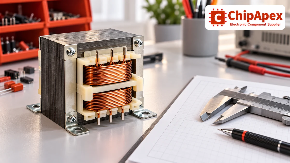
For a single-phase winding, apparent power is S = V RMS × I RMS, expressed in volt-amperes. A secondary rated at 12 VAC and 2 A represents 24 VA under its specified conditions. A 24 VAC, 1 A winding also represents 24 VA, but it supplies a different voltage and current.
For multiple loaded secondaries, calculate the contribution of each winding and follow the manufacturer’s simultaneous-loading limits. A catalog may specify series and parallel alternatives for the same windings. Those alternatives are not additional independent capacities to add together.
Watts describe real power. For a load with power factor below one, watts and VA differ. Distorted current from rectifier charging pulses further complicates sizing because winding heating follows RMS current. A 24 W DC output requirement therefore does not by itself establish that a 24 VA transformer is sufficient.
Avoid selecting a universal percentage of spare capacity without considering the load. Establish continuous loading, thermal conditions and transient requirements, then use the manufacturer’s sizing guidance and verify the assembled design.
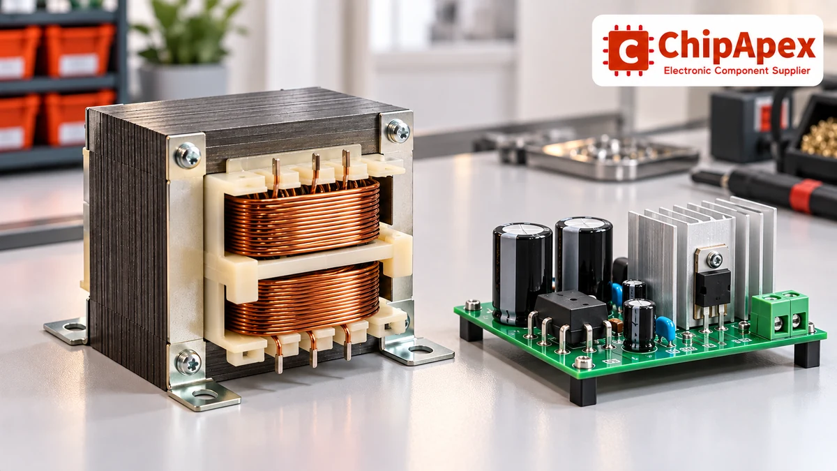
A bridge rectifier and reservoir capacitor draw current in pulses. The secondary RMS current can exceed the DC load current, and the relationship depends on the circuit. Use the appropriate rectifier/filter calculation rather than a single AC-to-DC conversion factor for all supplies.
The no-load peak of an ideal sinusoidal secondary is approximately √2 times its RMS voltage. In a real bridge supply, diode drops, source impedance, ripple and load current affect the available DC voltage. This peak relationship is useful for initial voltage checks, but it is not a complete regulator-input or capacitor-rating calculation.
Check two ends of operation. At low mains voltage and full load, allow enough voltage above the regulator’s dropout requirement through the ripple trough. At high mains voltage and light load, verify the maximum capacitor and regulator input voltages. Transformer regulation can raise the light-load output above the nominal full-load secondary voltage.
The manufacturer’s rectifier design guide explains why secondary current and voltage depend on the rectifier and filter configuration. Use the chosen parts’ data for final calculations, including diode surge capability and capacitor ripple-current rating.
Compare related diode options only after the topology and electrical stress are defined. A rectifier’s current, reverse voltage and thermal requirements must be satisfied together.
| Construction | Electrical relationship | Main selection implication |
|---|---|---|
| Separate primary and secondary windings | Energy transfers magnetically across the winding separation | Can provide galvanic isolation when designed and rated for the required application |
| Autotransformer | Input and output share part of a winding | Voltage conversion without galvanic isolation |
| Multiple isolated secondaries | Separate output winding circuits | Check isolation between all relevant winding pairs |
A turns ratio or a dielectric test value alone does not establish that a transformer satisfies every safety requirement of the finished equipment. Review the insulation system, approvals, working voltage, creepage and clearance conditions, and any required protective construction for the actual application.
Primary-to-secondary capacitance can couple noise across an isolated transformer. An electrostatic screen or suitable winding structure can affect that coupling, but neither removes the need for a complete EMC design. A shield connection must follow the component’s instructions.
An isolation transformer also does not make every secondary arrangement touch-safe. Secondary voltage, grounding, accessible connections and available fault energy still matter. Specify the required equipment function and qualification rather than asking for a generic “safe transformer.”
Voltage regulation describes the output-voltage change with loading under stated input conditions. One common expression is (V no-load − V full-load) ÷ V full-load × 100%. Confirm the definition used in the selected datasheet before comparing figures.
A higher no-load output can explain why a new transformer reads above its nominal voltage on a multimeter. It can also increase the voltage stress of a lightly loaded DC supply. Review the complete tolerance stack: mains variation, winding regulation, rectifier behavior and loading.
Temperature rise is specified relative to an ambient and test condition. Insulation-system temperature, maximum ambient and allowable rise are related but distinct limits. A nominal VA rating cannot be carried unchanged into every enclosure, altitude or cooling arrangement. Obtain the relevant derating information and measure temperatures in the intended assembly.
Compare toroidal, EI-laminated, split-bobbin and encapsulated forms against the design constraints. Footprint, height, mass, stray field, interwinding capacitance, mounting and inrush can differ. These are product-specific tradeoffs, so avoid assuming every toroid or encapsulated transformer performs identically.
A 60 Hz-only transformer should not be assumed suitable at the same voltage on 50 Hz. Lower frequency at an unchanged voltage changes core-flux conditions and can lead to excess magnetizing current and heating. Use a 50/60 Hz-rated variant or obtain explicit manufacturer approval for the proposed operating condition.
A passive transformer does not convert frequency. A 50 Hz source remains 50 Hz at the secondary, even if its voltage changes. Voltage conversion alone therefore cannot solve a frequency incompatibility in connected equipment.
Dual primaries may support series operation for a higher input voltage and parallel operation for a lower input voltage. Dual secondaries may similarly offer higher voltage in series or greater current in parallel, within their ratings. Observe the phasing marks and the exact wiring diagram. Incorrectly paralleled windings can create a severe circulating current.
The dual-winding connection reference illustrates the role of winding phase. Its examples should be applied only through the specific transformer’s own terminal identification and connection instructions.
Magnetizing inrush occurs when the transformer is energized. Residual core flux and the point on the AC waveform at switching influence its magnitude. It can occur with little secondary load.
The secondary circuit can introduce another transient. Reservoir capacitors charge, motors accelerate and contactors draw pickup current. A control transformer may need to maintain enough secondary voltage during that event for a contactor to close reliably, even when its steady-state holding load is modest.
Coordinate the primary switch, protective device, rectifier and any inrush-limiting component with the actual startup profile. Do not fix nuisance tripping by simply increasing protection beyond the permitted design. Check whether the cause is normal inrush, an incorrect winding connection, an unsuitable frequency or a fault.
Allow clearance for winding leads, connectors and insulation. Follow mounting instructions for toroidal hardware, including measures that prevent an unintended conductive loop around the core. Keep sensitive analog circuitry away from avoidable magnetic coupling and evaluate mechanical hum in the actual enclosure.
Specify PCB pin spacing, chassis fixing centers, maximum height, mass and connector arrangement on the RFQ. Consider assembly handling and service access as well as whether the part physically fits.
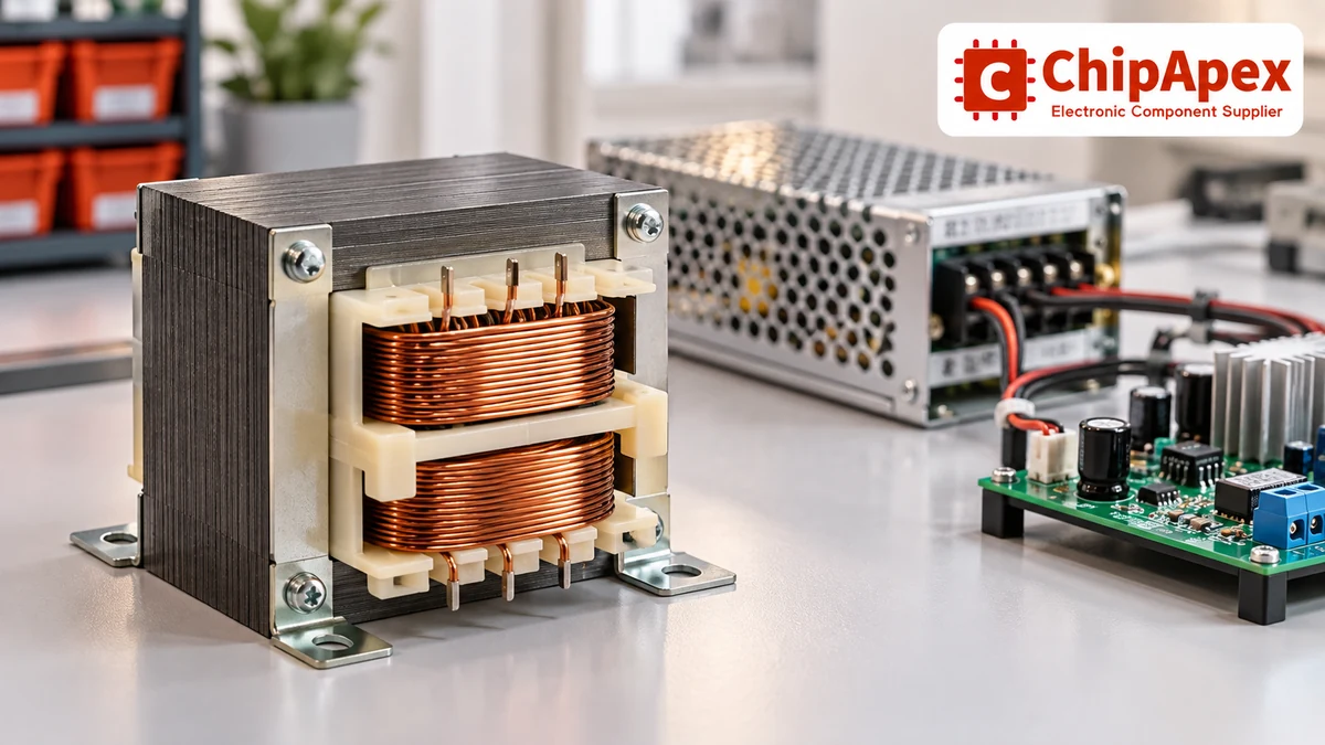
If the project needs a complete regulated mains-to-DC supply, assess an industrial ac to dc converter as a separate architecture option. A bare transformer leaves rectification, regulation, protection and much of the assembly-level design to the equipment developer.
VA is apparent power, calculated from RMS voltage and current for a single-phase winding. Watts are real power. They coincide for an ideal unity-power-factor load, but can differ with other loads. A rectified DC supply adds waveform and loss considerations, so its output watts cannot be used as the transformer VA rating without further calculation.
Many transformers specify nominal secondary voltage at a stated load. With little current flowing, winding losses and voltage drops are lower, so the measured voltage can rise. Check the regulation specification and input voltage, then evaluate high-line, light-load voltage stress on the downstream components.
Follow the manufacturer’s connection instructions. Transformers designed for dual-primary series or parallel operation may require both windings to be connected for the stated rating. Using one winding alone can change heating and regulation. Do not infer permissible wiring from the voltage marking without checking the diagram.
No. Its input and output share an electrical winding path. It can change voltage without providing galvanic isolation. If the equipment requires a defined isolation barrier, choose a transformer designed and rated for that purpose and verify its suitability within the complete equipment design.
No. A passive transformer changes voltage and current relationships while retaining the input frequency. Equipment that requires another frequency needs a suitable frequency-conversion solution or a compatible redesign. Check both the transformer and the connected load when adapting equipment for a different mains system.
Provide input range and frequency, all secondary voltages and RMS currents, load type, duty cycle, ambient conditions, insulation requirements and mechanical constraints. Include the rectifier topology for a DC supply. Approved part numbers, quantity, documentation needs and the required delivery schedule help narrow the enquiry.
Send ChipApex the electrical specification, drawing and approved part numbers, together with quantity and delivery requirements. Request the exact manufacturer’s datasheet and confirmation of the quoted winding arrangement. Evaluate proposed alternatives against insulation, startup and thermal requirements before approving a substitution.

A pressure transducer turns pressure into an electrical signal that a controller can read. Inside the device, a sensing element responds to pressure; the electronics then provide a specified voltage, current, or digital output. The output format m...
View details
Understand RF attenuator dB values, fixed and programmable types, impedance, power limits and noise tradeoffs before choosing parts for an RF signal path.
View details
Learn how digital to analog converters work, compare DAC types and selection criteria, and send your part number or BOM to ChipApex for a component quote.
View details
Understand how oscillators generate timing signals, how they differ from crystals, and which frequency, output and stability specs matter when choosing one.
View details
The activity of extra discounts on wholesale prices is in full swing…
Please fill in your contact information and we will send you the latest wholesale price list.

