 ChipApex | Global Electronic Components Supplier

SEARCH
Search Product
Search Post
— IC芯片 | 连接器 | 传感器 | 被动器件 —
Search productSearch post
— IC芯片 | 连接器 | 传感器 | 被动器件 —
The trend of science and technology is changing rapidly.
A temperature sensor converts its own temperature into a resistance, voltage or digital reading. The main contact-sensing choices are thermistors, RTDs, thermocouples and semiconductor ICs. Select between them by the temperature range, total measurement error, response time, mounting environment and interface the complete system must support.
The sensing element’s accuracy is only part of the result. A well-specified sensor can report the wrong target temperature if it sits beside a hot regulator, has poor contact with a surface or uses the wrong conversion curve. Start with the location being measured, then choose the sensing technology and electronics together.
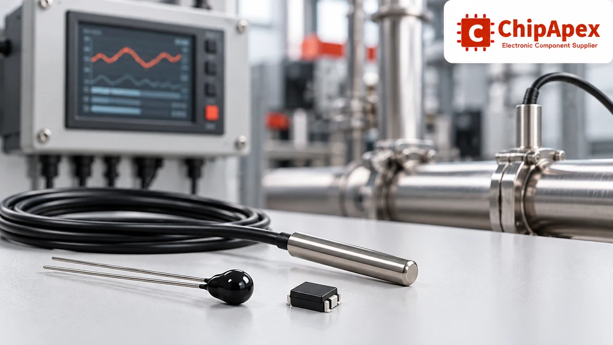
| Type | Electrical behavior | Useful strengths | Design work to allow for |
|---|---|---|---|
| NTC thermistor | Resistance decreases as temperature rises | High sensitivity over a selected range; compact sensing elements | Nonlinear conversion, tolerance and excitation heating |
| Platinum RTD | Resistance increases predictably with temperature | Repeatability, stability and established resistance curves | Excitation, lead resistance and precision measurement |
| Thermocouple | Small thermoelectric voltage depends on junction temperatures | High-temperature sensing and varied probe constructions | Cold-junction compensation, low-level amplification and correct wire type |
| Temperature IC | Semiconductor sensing produces an analog or digital output | Convenient board-level integration; calibrated options | Supply, interface, package thermal path and specified accuracy band |
These are technology-level comparisons. Actual limits depend on the element, package, probe construction and qualification. Avoid using a broad family temperature range as the allowable range of every part in that family.
ChipApex’s temperature sensors category can be used to narrow the component search, but the final decision should follow the complete datasheet. For an off-board probe, specify the sheath, cable and attachment method as carefully as the sensing element.
An NTC thermistor changes resistance strongly with temperature, making it useful in battery monitoring, appliance control and thermal protection. A voltage divider and ADC can form a practical measurement circuit. The conversion must use the resistance–temperature relationship for the selected part.
The nominal resistance, usually referenced to a stated temperature, does not fully identify the curve. Two 10 kΩ thermistors can behave differently away from that reference point. Check resistance tolerance, the specified beta value and temperature interval, or the supplied resistance table and Steinhart–Hart coefficients.
When comparing ntc thermistors, include body style and dissipation information. A small bead, an SMD component and an encapsulated cable probe can share a nominal resistance while responding differently to an identical temperature step.
Excitation creates heat. In a simple constant-current illustration, the element dissipation is P = I²R. Reducing current can reduce self-heating but also reduces the signal available to the measurement circuit. Choose the excitation and sampling method against the required noise performance and the thermal conditions around the sensor.
PTC thermistors have a positive temperature coefficient, but many are selected for protection, switching or heating behavior. Check their intended function before treating them as interchangeable precision measurement elements.
A platinum RTD uses a repeatable resistance change to infer temperature. Pt100 and Pt1000 identify nominal resistances of 100 Ω and 1,000 Ω at 0°C. Accuracy class, curve standard, element construction and the complete probe rating still need to be specified.
In a two-wire measurement, the lead resistance is included with the sensor resistance. This can become significant with long cables or low-resistance elements. A three-wire circuit can compensate for lead resistance under its matching assumptions. A four-wire measurement separates excitation and sensing paths to reduce the influence of lead resistance.
Check whether the chosen measurement circuit actually supports the required wiring arrangement. A four-wire probe connected as a simple two-wire resistor will not deliver the benefit of a four-wire measurement. Connector and terminal resistance, reference-resistor drift and current-source behavior also belong in the error budget.
A ratiometric ADC circuit can reduce sensitivity to excitation-current variation by measuring the sensor against a reference driven by the same current. It still needs suitable input filtering, settling time and layout. These tradeoffs are developed in this RTD measurement design reference.
A thermocouple uses dissimilar conductors to produce a temperature-dependent voltage. The measured signal relates to the sensing and reference junction temperatures. Measuring the voltage alone is therefore insufficient for an absolute temperature result unless the reference junction is controlled or compensated.
Cold-junction compensation measures the temperature where the thermocouple conductors connect to the measurement system and applies the appropriate conversion. Keep that region thermally uniform. A compensation sensor beside a warm component may not represent the actual connector temperature.
Choose the thermocouple type for the intended range, atmosphere, stability needs and probe construction. Type letters identify different material systems and conversion functions. Use appropriate extension wire and connectors, and check polarity throughout the assembly.
Grounded and ungrounded junction constructions also change the electrical connection to the sheath and the response behavior. Where equipment potentials differ, assess input common-mode limits and isolation requirements. A metal-sheathed probe should not be assumed electrically isolated simply because it is a temperature sensor.
For high temperature sensors, check the whole assembly. The element may tolerate a temperature that the insulation, cable transition or connector cannot. Continuous operation, short exposure and storage limits can also differ.
An analog temperature IC can produce a specified voltage or current relationship, while a digital device incorporates conversion and a communication interface. Depending on the model, the interface may be I²C, SMBus, SPI or 1-Wire. Confirm the actual bus and electrical requirements; a digital output does not imply protocol compatibility.
For a digital design, check supply range, logic thresholds, address options, conversion time, standby current and fault behavior. Resolution describes the output step size. Accuracy describes closeness to the actual temperature under specified conditions. A fine resolution does not establish a matching absolute accuracy.
An IC normally measures its die temperature. The package and leads determine how closely that follows a board, enclosure or air temperature. A surface-mount sensor near a processor can be useful for board monitoring but misleading as an ambient-air measurement.
Remote-diode monitoring is another arrangement: a sensor IC measures a suitable junction elsewhere in the system. This requires compatibility with the remote junction and the manufacturer’s recommended connections, filtering and layout.
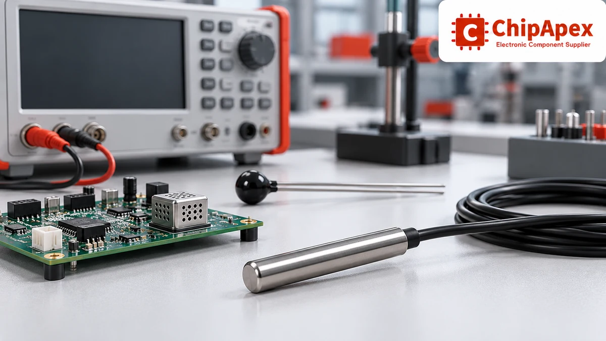
Include sensor tolerance, conversion and reference errors, lead resistance, noise, self-heating, calibration residuals and thermal gradients. Some contributions vary with temperature or operating mode. Combining them as a simple sum or root-sum-square requires a justified worst-case or statistical model.
For example, an application requiring ±1°C at the target cannot assign the entire allowance to a ±1°C sensing element while ignoring electronics and mounting error. Allocate a budget to each contribution and evaluate the complete assembly at relevant temperatures.
Calibration can correct repeatable offsets or curve differences at the calibrated conditions. It cannot make poor thermal coupling disappear or guarantee response during a fast temperature change. Specify whether calibration applies to the bare element, the probe or the complete installed measurement chain.
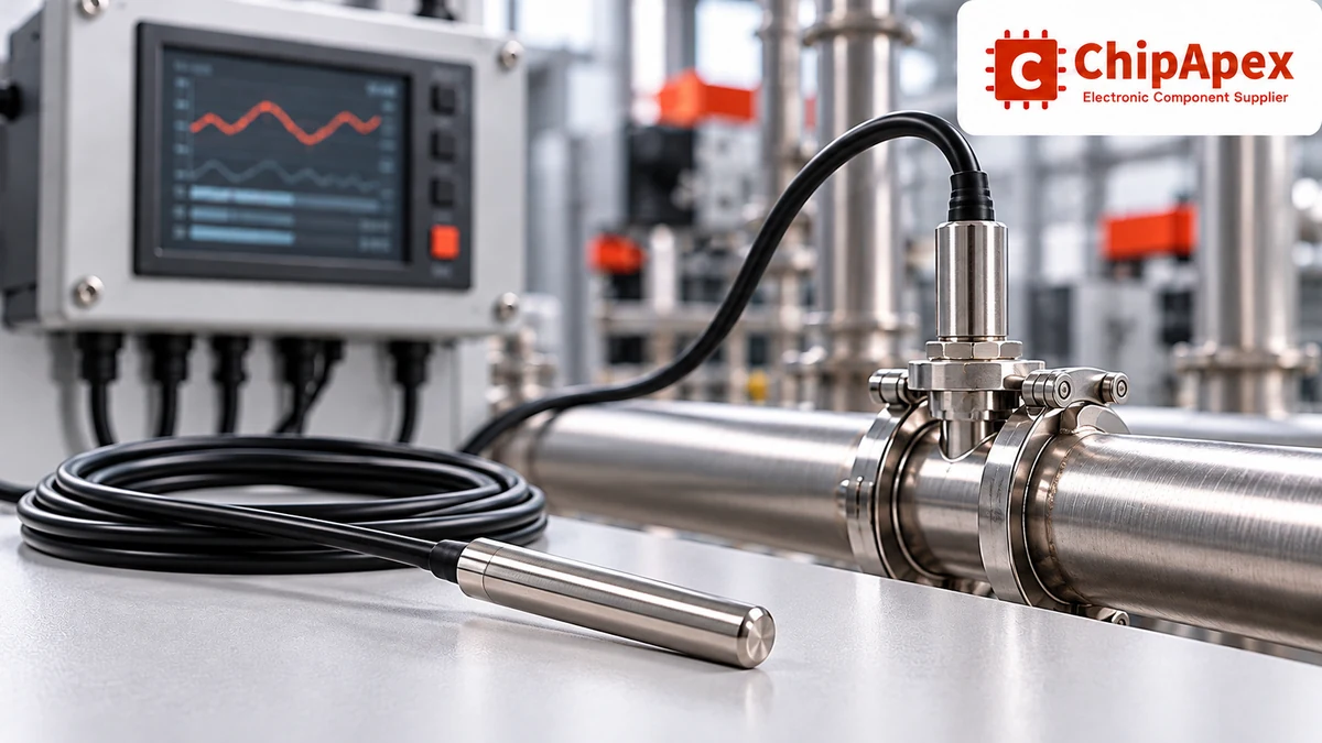
The sensor measures heat reaching its element. Adhesive thickness, air gaps, sheath mass, airflow and immersion depth affect that transfer. A fast conversion time in a datasheet should not be mistaken for the thermal response time of an installed probe.
For a surface measurement, define the attachment method and evaluate contact repeatability. For air measurement, reduce unwanted conduction from a warm PCB or enclosure. For a liquid probe, check immersion, material compatibility and the permitted pressure and sealing conditions.
A thermal time constant is often defined around reaching 63.2% of a temperature step for a first-order response. Actual assemblies may have several thermal paths and time constants. Compare response figures only when the test medium, airflow or fluid motion, and mounting conditions are comparable. This temperature measurement application guide discusses the role of self-heating and response conditions.
| Application requirement | Information to put on the enquiry |
|---|---|
| Temperature window | Normal, startup, fault, storage and transient exposure |
| Accuracy | Required system error over the actual operating band |
| Mechanical interface | PCB package, probe dimensions, sheath, thread or attachment |
| Electrical interface | Resistance curve, output type, supply and communication requirements |
| Environment | Fluid, pressure, humidity, vibration and required protection |
| Production control | Calibration evidence, traceability needs and acceptance test |
Do not approve an alternate by package and room-temperature value alone. Compare the full curve, tolerance band, response conditions and mechanical construction. For a probe assembly, confirm lead length and connector pinout as well.
Accuracy depends on the specific sensor, measurement electronics, calibration and mounting. Precision RTDs and calibrated semiconductor sensors can support demanding measurements in suitable temperature bands. Compare total system error over the required range instead of ranking entire sensor families by one headline specification.
Both infer temperature from resistance. An NTC thermistor generally provides a larger, nonlinear resistance change over a selected range. A platinum RTD follows an established metal resistance curve and is often chosen for stability and repeatability. Each requires the appropriate excitation and conversion method.
The thermocouple element generates its sensing voltage without electrical excitation. The amplifier, ADC, compensation sensor and communication circuitry normally need power. A thermocouple transmitter or digital converter therefore has a supply requirement even though the thermocouple itself is a self-generating element.
Yes, when its physical installation lets its temperature follow the air being measured. Heat from the PCB, supply dissipation, nearby components and enclosure surfaces can introduce an offset. Evaluate the installed assembly under representative airflow and power conditions rather than relying only on the IC’s calibrated accuracy.
No. They can differ in beta value, resistance curve, tolerance, package, dissipation constant and operating range. Probe assemblies can also have different cables and seals. Compare the full resistance–temperature information and mechanical requirements before substituting one 10 kΩ sensor for another.
Analog output can suit an existing ADC architecture, but requires attention to signal integrity and conversion errors. Digital output simplifies some conversion work while adding bus, address and timing requirements. Cable length, noise, power and the host controller’s interfaces should guide the decision.
Provide ChipApex with the temperature range, required system accuracy, sensor or probe style, interface, quantity and preferred part numbers. Include cable and connector details for assemblies. Request confirmation of the exact variant and its datasheet before treating any alternative as a qualified replacement.
A battery BMS, or battery management system, monitors a battery and controls how it is used within defined operating limits. It measures conditions such as cell voltage, pack current and temperature. Depending on the design, it can also balance ce...
View details
Compare RC, crystal and MEMS oscillator circuits. Check ppm, jitter, load capacitance, startup margin and output compatibility before choosing a clock source.
View details
Practical MCU selection guide for engineers: compare STM32, ESP32 & NXP, avoid counterfeits, and ensure supply chain reliability. Authored by ChipApex FAE.
View details
See how a MEMS gyroscope measures angular rate, why its angle estimate drifts, and which range, noise, interface and temperature specs to compare.
View details
The activity of extra discounts on wholesale prices is in full swing…
Please fill in your contact information and we will send you the latest wholesale price list.

