 ChipApex | Global Electronic Components Supplier

SEARCH
Search Product
Search Post
— IC芯片 | 连接器 | 传感器 | 被动器件 —
Search productSearch post
— IC芯片 | 连接器 | 传感器 | 被动器件 —
The trend of science and technology is changing rapidly.
A gyroscope measures angular motion: how quickly an object rotates around an axis. In a common MEMS gyroscope, a tiny structure is driven to vibrate. Rotation produces a Coriolis response in a second direction, and the sensor electronics convert that response into an angular-rate reading. The reading can be integrated to estimate a change in angle over time.
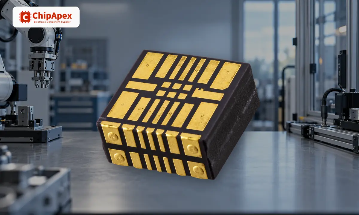
Most electronic gyroscopes used in embedded products report angular rate, often in degrees per second or radians per second. They do not directly report absolute orientation. Software can integrate the rate to estimate angle, but bias and noise cause the estimate to drift. A fixed reference or another sensor can help correct that drift in a complete system.
The number of axes tells you which rotations the device can sense. A three-axis gyro measures rotation about three perpendicular axes, though the meaning of each axis depends on how the package is mounted on the board.
A MEMS gyro drives a microscopic proof mass back and forth. When the device rotates, Coriolis force causes a small motion perpendicular to the driven motion. Sensing elements detect that change, and the electronics estimate angular rate. This is a functional explanation, not a depiction of a particular ChipApex-listed part's internal structure. Analog Devices' gyroscope explanation shows the sensing principle in a specific device family.
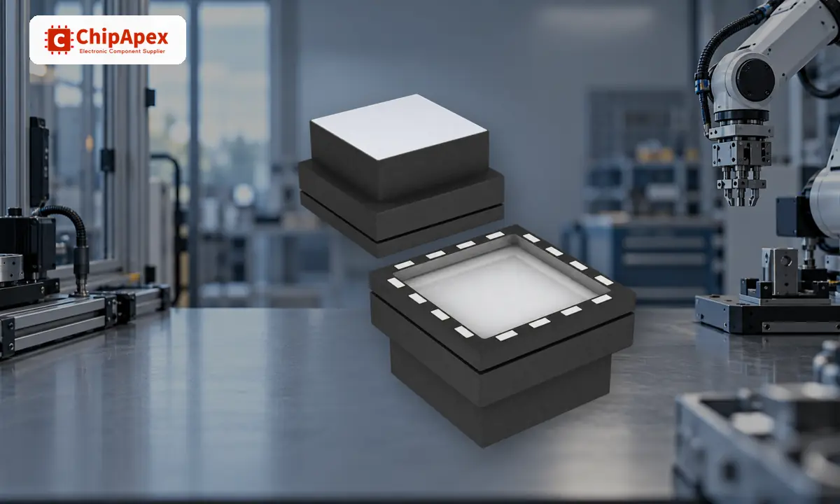
A gyro responds to rotation rate. An accelerometers device measures acceleration, including the effect of gravity when the sensor is stationary. Each has a different weakness: a gyro-based angle estimate drifts with time, while accelerometer-based tilt estimates can be disturbed by movement and vibration.
An inertial measurement unit may combine a gyroscope and accelerometer in one package. Sensor fusion can use their complementary measurements to make an orientation estimate more useful. The quality of that estimate still depends on calibration, mounting, motion, and the algorithm.
Gyros appear in robotics, camera stabilization, navigation equipment, motion tracking, and industrial monitoring. The right sensor depends on the motion, not just the application label. A slow positioning platform may value low bias drift; a fast-moving mechanism may need a wider full-scale range. Mechanical vibration can also affect readings, so test in the intended mounting position.
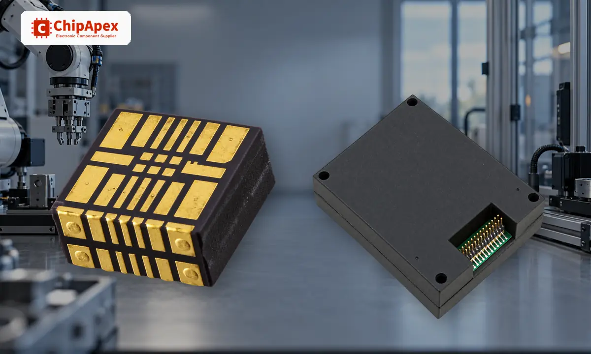
Compare axis count, full-scale range, noise density, bias stability, sample rate, interface, supply voltage, package, and temperature behavior. The datasheet's range must cover the fastest expected rotation, while its noise and bias must suit the measurement duration. A wider range alone does not make a sensor more accurate.
For sourcing, send ChipApex the full part number if the design is fixed. For a new design, state the motion range, interface, supply, package limits, and quantity. A category photo is only a visual aid; confirm the exact part's dimensions and electrical characteristics in its datasheet.
An electronic gyro usually measures angular rate, which is rotational speed around an axis. Software can integrate that rate to estimate a change in angle, but the estimate accumulates error unless corrected.
It senses rotation around three perpendicular axes. Those axes are defined relative to the package, so board orientation matters when interpreting the data.
A gyro measures angular motion. An accelerometer is the sensor commonly used to sense the direction of gravity when movement is small enough for a stable tilt estimate.
Small offsets and noise remain even when the sensor is still. Integrating those errors over time creates angle drift. Calibration and other references can reduce the effect.
No. Performance varies widely by part. Long-duration navigation may require much lower bias drift and additional references than a basic motion-control application.
Learn how rectifiers convert AC to DC, compare half-wave and bridge circuits, and select voltage, current, recovery and thermal ratings for your design.
View details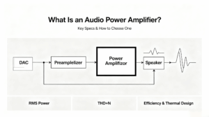
Learn what an audio power amplifier is, the differences between Class D and AB, and how to choose the right IC. Includes PCB layout tips and part recommendations. Shop at ChipApex.
View details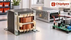
Select power transformers by input frequency, secondary VA, rectifier load, isolation, regulation and inrush. Build a clearer specification for your next RFQ.
View details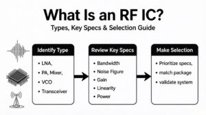
Learn what an RF IC is, how LNAs, PAs, mixers, attenuators and transceivers differ, and how to choose the right RF component. Includes verified part numbers and layout tips.
View details
The activity of extra discounts on wholesale prices is in full swing…
Please fill in your contact information and we will send you the latest wholesale price list.

