 ChipApex | Global Electronic Components Supplier

SEARCH
Search Product
Search Post
— IC芯片 | 连接器 | 传感器 | 被动器件 —
Search productSearch post
— IC芯片 | 连接器 | 传感器 | 被动器件 —
The trend of science and technology is changing rapidly.
A rocker switch opens, closes or changes an electrical circuit when its actuator rocks between positions. To choose one, match the contact arrangement, AC or DC load rating, operating action, illumination circuit and panel cutout. A matching shape or printed current value alone does not establish that a replacement is suitable.
The selection becomes easier when the electrical circuit and the mechanical drawing are reviewed together. A switch can carry the required current yet fit poorly in the panel. An illuminated model can fit perfectly while its lamp requires a different supply. Both problems should be resolved before a production order.
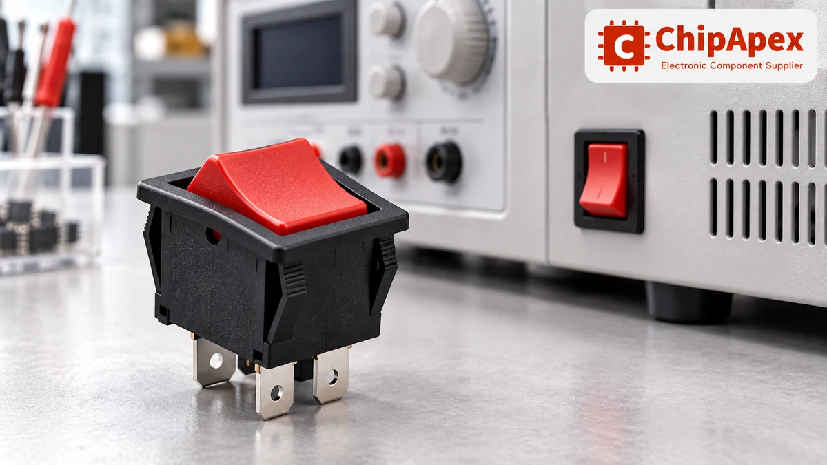
Start with the actual load: supply voltage, normal current, startup current, switching frequency and load type. Record whether the rocker directly switches power or sends a signal to a controller. A dry-contact logic input and a motor supply place very different demands on the contacts.
For an appliance power control, the visible actuator is only one part of the specification. Check the complete part number, its contact circuit and its approved load conditions. The power switch rocker category is a useful starting point for comparing the required function with available package styles.
Distinguish maintained action from momentary action. A maintained switch stays where the operator leaves it. A momentary position returns when released. Catalog notation often uses parentheses for a momentary position, such as ON–OFF–(ON), but confirm the manufacturer’s circuit table because naming conventions can differ.
A pole is a separate circuit controlled by the actuator. A throw is a connection available to that circuit. The number of terminals can also include illumination connections, so counting pins is an unreliable way to identify the switching function.
| Contact arrangement | What it normally does | Selection question |
|---|---|---|
| SPST | Opens or closes one circuit | Is simple ON/OFF control sufficient? |
| SPDT | Connects one common terminal to either of two paths | Is a changeover function required? |
| DPST | Opens or closes two circuits together | Must two conductors be switched simultaneously? |
| DPDT | Changes two separate circuits between paths | Does the full circuit require two changeover poles? |
A three-position rocker is not automatically a three-throw switch. An ON–OFF–ON SPDT device has two active paths and a center-off position. Also check whether changeover contacts are break-before-make or make-before-break when a brief overlap could matter to the circuit.
When actuator style is flexible, electrical toggle switches can serve similar maintained or momentary control functions. Compare their mounting and operation requirements independently; a shared contact arrangement does not make the two styles mechanically interchangeable.
Use the rating specified for the supply type and load. A current rating at 125 VAC does not establish a DC switching capability. AC current crosses zero periodically, while interrupting a DC circuit can sustain an arc under different conditions. Obtain an explicit DC rating when the application uses DC.
Resistive, inductive and capacitive loads also behave differently. A heater may have a relatively steady operating load, whereas a motor or transformer can draw substantial startup current. A power supply’s input capacitor can produce a short charging surge. Select against the applicable load category and inrush conditions instead of applying an arbitrary current margin.
Check these details on the exact variant:
Mechanical life measures operation without the same electrical stress used in an electrical-life test. A high mechanical-cycle figure therefore cannot substitute for an electrical endurance rating. The distinction is explained in this manufacturer guide to switch endurance.
At the other end of the current range, a power-rated contact may perform poorly on a very small sensing current. Gold-plated signal contacts, minimum-load specifications and dual-rated options deserve attention when a rocker feeds a microcontroller or PLC input. A previously power-switched contact should not be assumed suitable for later use as a dry-circuit contact.
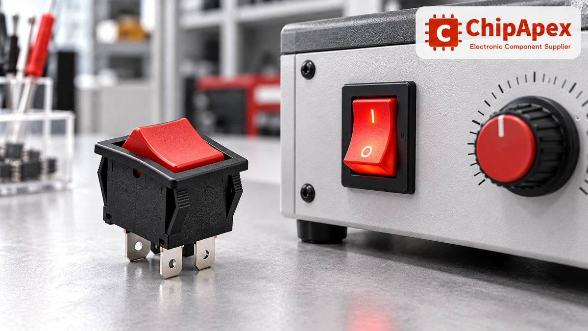
The lamp voltage and the contact rating are separate specifications. A switch may carry a relatively high load voltage while using a low-voltage LED, or it may contain a neon lamp intended for a particular AC supply. LED polarity and current limiting depend on the exact internal circuit.
| Illumination arrangement | Typical purpose | What to verify |
|---|---|---|
| Dependent illumination | Shows that the switched path is energized | Internal connection to the switching circuit |
| Independent illumination | Lights a legend or receives a separate status signal | Separate lamp terminals and supply requirements |
| Dual illumination | Separates backlighting from a second indication | Both lamp circuits, polarity and terminal identification |
An illuminated actuator does not prove that the connected machine is operating. A lamp connected after the switch may indicate available voltage while the load itself has failed. Define whether the operator needs power indication, position indication or feedback from the controlled equipment.
Use the manufacturer’s terminal diagram. Two illuminated rockers with the same number of terminals can have different internal connections. An external LED resistor is needed only when the chosen assembly does not already provide suitable current limiting. Lamp selection principles and resistor requirements are covered in this illumination application reference.

Match the specified panel opening rather than the outer bezel size. A bezel can conceal an opening that is too large, yet the retaining clips may fail to secure the switch. Cutout width, height, corner geometry and tolerances all affect retention.
Panel thickness is just as important. Snap-in clips are designed for a stated thickness range. Paint, powder coating, overlays and gaskets can change the finished stack. Confirm that the switch fully seats, resists expected operating forces and can be removed for service without damaging the panel.
Behind the panel, allow room for the switch body, terminals, insulation boots and the cable bend. A drawing showing only the body depth can underestimate the installed envelope. Also check spacing from neighboring controls so a hand, glove or accidental bump does not operate the wrong rocker.
For panel artwork, specify the orientation of I/O symbols, ON/OFF legends and any illuminated window. Inspect the sample in its installed position. A correctly wired switch with an upside-down legend can still create an avoidable operating error.
Quick-connect tabs suit harness assembly, but the mating receptacle must match the tab dimensions, current and retention requirements. Solder lugs, PCB pins, screw terminals and prewired leads each require different assembly clearances and process controls. Do not bend or heat a terminal beyond its component instructions.
Check where an ingress-protection rating applies. Some ratings cover the actuator side when mounted in the specified panel; the exposed rear terminals may need separate protection. A sealed switch does not automatically make the complete enclosure sealed. Gasket compression, panel finish and mounting orientation can affect the assembled result.
Verify operating temperature, humidity, vibration, cleaning agents and outdoor exposure against the chosen part. Process sealing for soldering or washing should also be checked separately from service-environment sealing. The qualification must match the environment the finished product will encounter.
A useful enquiry includes the manufacturer’s part number or a complete functional specification. For a new selection, provide contact arrangement, maintained or momentary positions, supply and load details, lamp requirements, cutout drawing, finished panel thickness, termination and expected environment.
If the rocker is only a user-interface input, compare the space and interaction requirements with tactile switches. A tactile input normally needs a controller to retain an ON/OFF state. That is a different design decision from directly switching a power circuit.
Before approving an alternate, compare the circuit diagram, rating conditions and mechanical drawing line by line. Follow with a sample fit check and load test under the intended conditions. Record the approved variant so later orders do not silently change lamp voltage, actuator action or terminal style.
Only when the manufacturer specifies an appropriate DC rating for that exact switch and load. An AC rating alone is insufficient. Confirm the DC voltage, current, load type and electrical endurance. If no suitable DC information is available, select another rated part instead of inferring compatibility from the printed AC current.
One possible arrangement uses two terminals for the switched path and another for the lamp return. Other internal circuits are possible, so three terminals do not define a universal wiring diagram. Identify the common, switched and lamp connections from the exact part’s datasheet before connecting it.
No. ON–OFF–ON normally adds a stable center-off position, whereas ON–ON changes between two active positions. Parentheses can indicate momentary action in either arrangement. Confirm the contact table, including connected terminals in each position, when replacing a switch or designing a harness.
Possible causes include an excessive load, unexpected startup current, a loose or unsuitable terminal connection, contact wear and a high local ambient temperature. Disconnect the supply before inspection. Compare the complete installed circuit with the switch and connector ratings; replacing the switch with the same outline may leave the cause unresolved.
The component rating applies under its stated mounting and test conditions. It does not establish the ingress rating of the complete panel or protect every exposed terminal. Verify the sealing surface, gasket, cutout and panel thickness, then validate the assembled enclosure for the intended exposure.
Send the full part number, clear markings, contact function, electrical load, lamp supply, terminal details and panel dimensions. Photos help identify construction, but they do not replace a circuit diagram or rating information. Note any symptoms and whether the old part was operating near a heat source.
Send ChipApex the required switch specification, quantity, target delivery date and any approved manufacturer part numbers. Include the cutout drawing and load conditions when requesting an alternate. Ask for the exact datasheet and variant details with the quotation so electrical and mechanical suitability can be reviewed before approval.
Understand how oscillators generate timing signals, how they differ from crystals, and which frequency, output and stability specs matter when choosing one.
View details
Select power transformers by input frequency, secondary VA, rectifier load, isolation, regulation and inrush. Build a clearer specification for your next RFQ.
View details
Learn how digital to analog converters work, compare DAC types and selection criteria, and send your part number or BOM to ChipApex for a component quote.
View details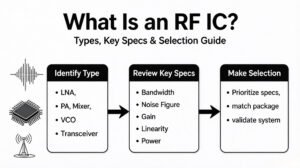
Learn what an RF IC is, how LNAs, PAs, mixers, attenuators and transceivers differ, and how to choose the right RF component. Includes verified part numbers and layout tips.
View details
The activity of extra discounts on wholesale prices is in full swing…
Please fill in your contact information and we will send you the latest wholesale price list.

