 ChipApex | Global Electronic Components Supplier

SEARCH
Search Product
Search Post
— IC芯片 | 连接器 | 传感器 | 被动器件 —
Search productSearch post
— IC芯片 | 连接器 | 传感器 | 被动器件 —
The trend of science and technology is changing rapidly.
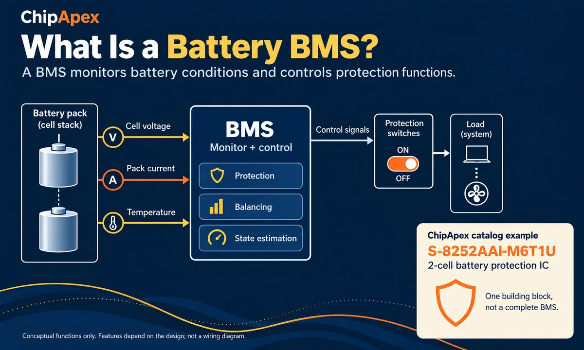
A battery BMS, or battery management system, monitors a battery and controls how it is used within defined operating limits. It measures conditions such as cell voltage, pack current and temperature. Depending on the design, it can also balance cells, estimate remaining charge and report faults to other equipment.
For a component buyer, the useful question is what the chosen device actually does. A small protection IC, a populated protection board and a complete BMS can all appear in battery-related catalogs, but they serve different requirements. That distinction matters when you turn a pack specification into a bill of materials.
A BMS checks the battery’s condition and responds when a measured value reaches a configured limit. Its scope depends on the pack: a simple design may provide basic protection, while a larger system can add balancing, charge estimation and communication.
| Function | What it does | What to check |
|---|---|---|
| Cell monitoring | Measures individual series-cell or parallel-group voltages. | Supported cell count and measurement accuracy. |
| Protection | Detects configured faults and commands a protective response. | Thresholds, delays, recovery conditions and switch arrangement. |
| Temperature monitoring | Uses temperature inputs to inform operating limits. | Sensor support, placement and charge/discharge temperature limits. |
| Cell balancing | Reduces differences in charge between series-connected cells. | Whether balancing is included, its method and available current. |
| State estimation | Estimates remaining charge and, in some systems, battery health. | Required gauge, software, calibration and battery characterization. |
| Communication | Reports measurements or faults to a controller or external system. | Interface, data format and required host support. |
When browsing ChipApex’s battery management system component category, check each device’s stated function. Being listed under battery management does not mean an IC includes all six functions.
The basic sequence is measurement, decision and response. Sensing circuitry collects battery data. Hardware protection logic or a controller compares those measurements with limits. The system can then change the permitted charge or discharge state, or report a fault.
Individual cell measurements matter because a normal-looking total pack voltage can hide an out-of-range cell. A pack can therefore need protection even when its combined terminal voltage seems reasonable.
The response also depends on the architecture. Small packs often use semiconductor switches; larger systems may use contactors and coordinate with a charger or load controller. The drawing above shows functional relationships, not a wiring diagram or a complete protection design.
These terms describe different jobs. Some ICs combine several jobs, so compare the functional description and application circuit rather than relying on the product name.
| Device or system | Main job | Do not assume it includes |
|---|---|---|
| Complete BMS | Coordinates the pack’s required monitoring and control functions. | Every possible feature; implementations vary. |
| Battery monitor | Measures battery conditions and makes data available. | Accurate remaining-capacity estimation without additional support. |
| Battery protector | Responds to specified fault conditions. | Cell balancing, a fuel gauge or a charging regulator. |
| Fuel gauge | Estimates remaining charge, capacity or runtime. | A complete power-disconnection circuit. |
| Battery charger | Regulates the charging process for the intended battery. | All protection and monitoring needed inside the pack. |
The separation between protection, measurement and gauging is also explained in this manufacturer’s guide to battery protectors, monitors and gauges.
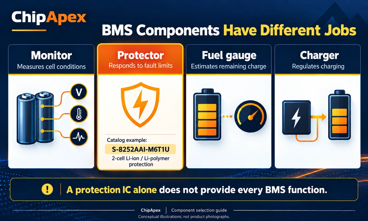
For example, a pack’s protection circuit may disconnect charging after a fault, but that action does not replace normal charge regulation. Select a compatible battery charger ic when the design requires a charging stage.
No. Balancing is a feature to verify, not something the BMS label guarantees. A basic protection device can detect voltage faults without correcting differences between cells.
Passive balancing removes a small amount of energy from higher-charge cells, usually through resistors. Active balancing transfers energy between cells or other parts of the pack. The passive-balancing technical explanation describes this distinction. Passive balancing adds heat; active balancing requires a more involved power-transfer circuit. Neither method restores capacity lost through cell damage or aging.
Balancing current matters when estimating correction time. As a simple planning example, removing a 100 mAh charge difference at a constant 50 mA takes two hours: 100 mAh ÷ 50 mA = 2 h. Real operation can take longer because balancing may be intermittent or limited by temperature and voltage conditions. This example is not a specification for the ChipApex part discussed below.
Record the cell chemistry, the cell manufacturer’s limits and the number of series-connected cell groups. A “2S” pack has two groups in series; cells within each group may be connected in parallel. The number of cells in parallel does not add voltage-measurement channels in the same way as adding a series group.
Do not choose a device from nominal pack voltage alone. Check its supported cell count, operating range and protection settings against the actual cells. A protection profile intended for one chemistry should not be assumed suitable for another.
Specify continuous charge current, continuous discharge current and the expected peak current with its duration. For current sensors, verify that the selected technology measures the pack’s DC current and supports the required direction and range. A conventional current transformer intended for AC measurement cannot directly measure steady DC.
Check the switching stage separately. Suitable mosfets must be assessed for voltage stress, gate-drive conditions, conduction losses and thermal behavior in the actual circuit. A protection IC’s cell-count rating does not establish the assembled board’s allowable pack current.
Some protection functions operate autonomously. Other designs need a host to configure the monitor, process measurements, manage communications or run application logic. Select a microcontroller ic around those specific tasks, including interface compatibility and low-power requirements.
State of charge (SOC) is an estimate of remaining charge. State of health (SOH) describes degradation relative to a reference condition and may use capacity or resistance, as explained in this BMS state-estimation overview. Neither should be treated as a direct reading from a voltage pin. Establish which device or software supplies the estimate before promising a percentage display.
Review detection delays, recovery behavior, temperature inputs, sleep current and what happens when a measurement connection is lost. A device can support the right chemistry and cell count while still needing configuration or external circuitry that the existing board does not provide.
ChipApex lists the ABLIC S-8252AAI-M6T1U as a two-cell lithium-ion/polymer battery protection IC in a SOT-23-6 package. This is a useful example of a component used within a battery protection design.
The S-8252 series datasheet describes protection for two series-connected lithium-ion or lithium-polymer cells, including overcharge, overdischarge and overcurrent detection. Check the selection tables for the exact suffix: family-level features do not establish every variant’s thresholds and delays.
This part should not be specified as a complete balancing BMS, a fuel gauge or a charger. If the product needs a battery-percentage display, cell balancing or communication with another controller, those requirements need their own supported functions in the overall design.
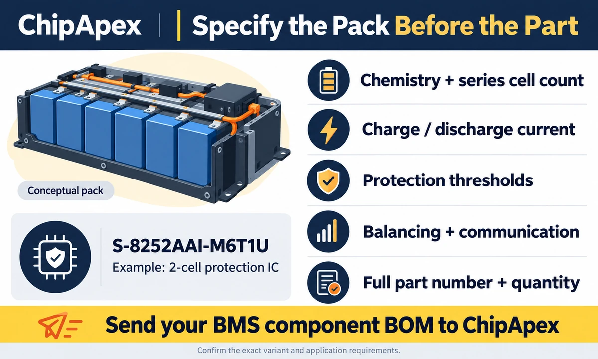
A request for a “BMS chip” leaves too much open. Send the complete manufacturer part number, including suffix, if you have one. For a new design or an alternative-part review, also provide:
For a replacement, attach the current datasheet or BOM line and identify which specifications cannot change. A matching package and cell count are only the beginning of a compatibility check.
BMS stands for battery management system. It is the circuitry and, where required, software that monitors and manages a battery. Its feature set can range from basic protection to a broader combination of monitoring, balancing, estimation and communication. Check the actual specification whenever the label is used.
A BMS can permit, stop or coordinate charging, but a charging regulator controls the charge process. Some products integrate both roles. Unless the specification explicitly includes charging regulation, plan for a separate compatible charger and verify how it interacts with the pack’s protection circuitry.
Only when the device and its configuration support the intended cells. LiFePO4 is a lithium-ion chemistry, but its operating and charging limits differ from other common lithium-ion chemistries. Check the cell specification, supported settings and complete circuit instead of relying on a broad “lithium battery” label.
Not unless it includes a supported gauging function or is combined with a suitable gauge or estimation system. Fault detection answers whether a limit has been reached. A percentage display needs an estimate of remaining charge, which is a different task and may require battery-specific characterization.
No. A higher board current rating does not increase the cells’ allowable current or remove limits in connectors, conductors and cooling. Every part of the assembled pack must support the intended load. Protection settings also need to remain appropriate for the cells and the application.
No. Also compare chemistry, fault thresholds and delays, current capability, temperature sensing, connection arrangement and any host communication requirements. For an IC replacement, add pinout, package and external-component requirements to that review. Matching “2S” or another series count does not establish interchangeability.
Preparing a battery-management BOM? Send your full part numbers, quantities and pack requirements to ChipApex. Identify whether you need protection, monitoring, charging, gauging or several of these functions so the quotation starts with the right component scope.
Choose an AC to DC converter by input range, output demand, isolation, efficiency and thermal derating. Compare architectures and check installation needs.
View details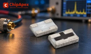
Understand RF attenuator dB values, fixed and programmable types, impedance, power limits and noise tradeoffs before choosing parts for an RF signal path.
View details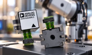
An inertial measurement unit (IMU) measures motion using an accelerometer and a gyroscope in one device or module. The accelerometer senses specific force, including the effect of gravity; the gyroscope senses angular rate. Software can combine th...
View details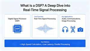
Learn how DSPs (Digital Signal Processors) enable real-time audio, industrial motor control, 5G communications & medical imaging. Compare DSP vs MCU, choose fixed vs floating-point DSPs, and source authentic DSP chips at ChipApex.
View details
The activity of extra discounts on wholesale prices is in full swing…
Please fill in your contact information and we will send you the latest wholesale price list.

