 ChipApex | Global Electronic Components Supplier

SEARCH
Search Product
Search Post
— IC芯片 | 连接器 | 传感器 | 被动器件 —
Search productSearch post
— IC芯片 | 连接器 | 传感器 | 被动器件 —
The trend of science and technology is changing rapidly.
An SPST toggle switch opens or closes one circuit. An SPDT toggle switch connects one common terminal to either of two paths. Choose between them by the circuit function you need, then check the AC or DC load rating, operating action, terminal layout and mounting dimensions before wiring.
ChipApex lists both circuit configurations within its Toggle Switches category. For a replacement or new design, the complete part number matters: similar-looking levers can operate different contacts and fit different PCB footprints.
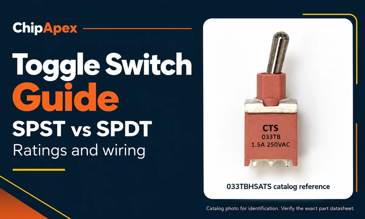
SPST provides one switched path. SPDT provides a changeover connection. “Pole” describes an independently controlled circuit; “throw” describes an available connection path.
| Feature | SPST | SPDT |
|---|---|---|
| Full name | Single pole, single throw | Single pole, double throw |
| Contact arrangement | One pair opens or closes | A common contact selects either of two contacts |
| Typical contact terminals | Two | Three |
| Common functions | ON-OFF; momentary variants also exist | ON-ON, ON-OFF-ON or momentary variants |
| Typical use | Enable or disable one circuit | Select between two control paths |
These terminal counts describe the switching contacts. Illumination or other functions can add terminals. A three-terminal device therefore needs a diagram before you identify it as SPDT. The manufacturer’s toggle switch overview explains the available pole-and-throw arrangements.
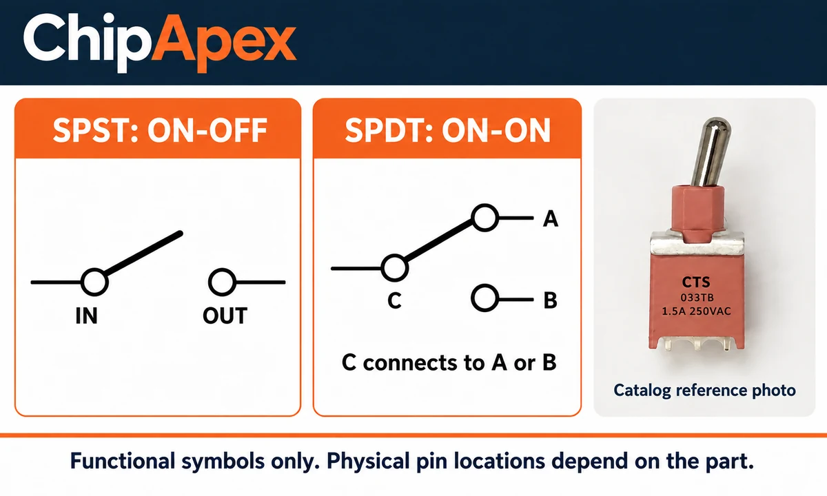
An ON-ON SPDT switch has two connected states: common-to-A and common-to-B. An ON-OFF-ON version adds a center position that opens both paths. A maintained switch stays where you leave it; a momentary position returns when you release the lever.
Parentheses commonly identify momentary positions, as in (ON)-OFF-(ON). Confirm the notation in the specific datasheet. Also check whether the contacts break before making the next connection or overlap during transfer. An ON-ON label alone does not establish the transfer sequence.
Use the specified current at the specified voltage, load type and operating conditions. A current figure on its own is insufficient for selection.
A rating such as 5 A at 125 VAC does not establish a 5 A DC rating. DC switching can sustain an arc when contacts open, so check the stated DC voltage and current for your application. Avoid converting an AC rating into a DC rating with a general rule.
Motors, lamps and capacitive inputs can draw a surge when switched on. Inductive loads also stress contacts when switched off. Check the applicable load rating and protection requirements. If a power load exceeds the toggle’s switching capacity, select an appropriate relay or driver and check the toggle against its control load.
A high-current switch can be a poor choice for a small logic signal. Check minimum applicable load and contact suitability. The manufacturer’s switch application precautions cover AC/DC differences, load effects and microcurrent contact reliability.
For example, a hypothetical 24 VDC, 2 A resistive load needs a switch explicitly suitable for that duty. Replacing it with a 2 A motor changes the selection problem, even though the running-current number is unchanged. Ask for the motor’s starting conditions and switching-duty requirements before choosing a part.
For a simple, suitably rated low-voltage DC load, place the SPST contacts in series with the supply path. The following example shows circuit relationships only.
DC positive → suitable fuse → SPST contact pair → load → DC return
The fuse, conductor size and connections must suit the actual circuit. This conceptual example does not specify mains wiring, protective earthing or a safety disconnect.
Identify common (C) and the two switched contacts (A and B). Do not assume the middle physical pin is common: terminal numbering and viewing orientation vary.
DC positive → suitable fuse → C
                              ├─ selected A → load A → DC return
                              └─ selected B → load B → DC return
In this selector example, an ON-ON switch supplies one branch in each stable position. An ON-OFF-ON version also provides a center-off state. Verify the switching sequence if overlapping branches could cause a fault.
On an isolated switch, continuity testing should show C-A connected in one ON position and C-B connected in the other. For a center-off version, neither pair should connect in the center. Use these checks alongside the manufacturer’s contact diagram.
An SPDT switch can also provide ON-OFF control using C and one throw, with the unused terminal insulated. Check space and connection security. Never use this simple branch-selector example to join independent power sources or reverse a motor; those applications need a circuit designed for the task.
After choosing the contact function, compare the mechanical drawing with the PCB or enclosure. A matching electrical rating does not make two switches mechanically interchangeable.
| Installation | What to verify | Common mismatch |
|---|---|---|
| PCB mounting | Pin pitch, hole pattern, body clearance, orientation and soldering conditions | Right-angle and vertical versions use different footprints |
| Panel mounting | Cutout, bushing thread, usable thread length, panel thickness and hardware | The bushing fits the hole but cannot clamp the panel |
| Wired terminals | Terminal style, compatible connection method, insulation and strain relief | A connector fits loosely or leaves exposed live metal |
| Exposed environments | Specified sealing boundary, mounting conditions and temperature range | A front-panel seal is assumed to protect the entire assembly |
Also distinguish mechanical life from electrical life. A no-load operating-cycle figure does not establish contact life while switching your load. Use the specified test conditions when comparing parts.
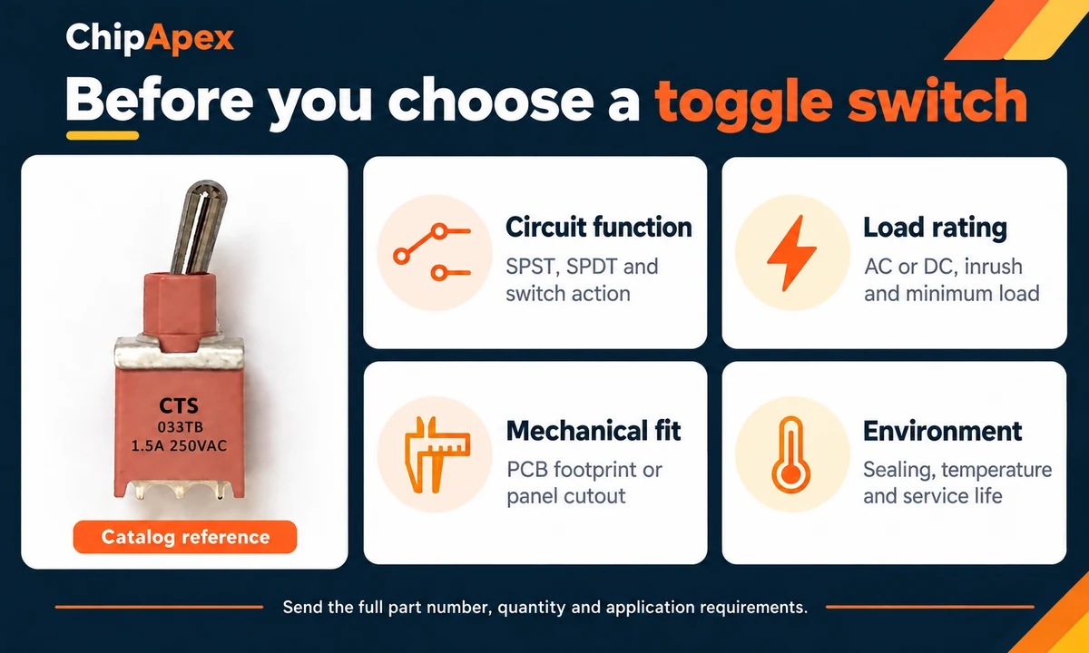
The ChipApex listing for 033TBHSATS identifies an SPDT, ON-ON toggle switch with right-angle through-hole mounting and PC-pin termination. That makes it a useful example of why contact function and mounting style belong in the same selection check.
An ON-ON part does not provide a center-off position. A right-angle PCB part also needs a compatible footprint; a panel-switch drawing cannot establish its fit. Confirm the complete manufacturer drawing and ordering suffix before approving a replacement. Catalog presence does not establish current stock or a particular delivery date.
Often, if you use the common contact and one throw. The replacement must meet the circuit’s electrical requirements and fit the installation. Insulate the unused terminal, confirm the operating action and check the pinout. Similar lever positions do not guarantee identical internal connections.
No. Three pins can represent three SPDT contacts, or two switching contacts plus a connection for illumination. Identify the part number and read its terminal diagram. Counting pins is a useful first observation, but it cannot establish the function of an unfamiliar switch.
No. SPDT describes the contact arrangement. An ON-ON version connects common to one throw in each stable position. A center-off version must specify an action such as ON-OFF-ON. Select the operating action separately from the number of poles and throws.
Check for an explicit DC rating applicable to the intended load. A lower supply voltage does not, by itself, establish DC switching capability. If the datasheet lacks the needed rating, obtain manufacturer confirmation or choose a part with a documented rating for the application.
A single SPDT contact set cannot directly reverse both motor connections in the usual two-wire arrangement. Reversing applications commonly use a suitably rated DPDT circuit or a motor driver. Include stall current, switching sequence and protection requirements in the design; a branch-selector diagram is insufficient.
Possible causes include loose connections, damaged contacts, unsuitable loading or a switch intended for a different signal level. Disconnect power before checking wiring and contact continuity. Compare the actual load with the part’s documented limits. Replace a damaged switch and resolve the cause before returning the equipment to service.
Send ChipApex the complete part number or required contact function, quantity, supply voltage, load details and mounting drawing. For a replacement, include the existing switch’s markings and dimensions. These details help narrow the search to parts that meet the electrical requirements and fit the assembly.
Compare RC, crystal and MEMS oscillator circuits. Check ppm, jitter, load capacitance, startup margin and output compatibility before choosing a clock source.
View details
Learn how audio amplifiers work, compare Class AB vs. Class D, and discover key metrics (THD+N, SNR). Source authentic TI/ST audio ICs at ChipApex for your design.
View details
Choose an AC to DC converter by input range, output demand, isolation, efficiency and thermal derating. Compare architectures and check installation needs.
View details
Learn how a diode conducts, how to identify anode and cathode, and when to choose rectifier, TVS, Zener or photodiode types for a circuit.
View details
The activity of extra discounts on wholesale prices is in full swing…
Please fill in your contact information and we will send you the latest wholesale price list.

