 ChipApex | Global Electronic Components Supplier

SEARCH
Search Product
Search Post
— IC芯片 | 连接器 | 传感器 | 被动器件 —
Search productSearch post
— IC芯片 | 连接器 | 传感器 | 被动器件 —
The trend of science and technology is changing rapidly.
A tactile switch gives physical feedback as its contact mechanism changes state. Most PCB tact switches are momentary, normally open devices used for low-power user inputs. Select one by operating force, travel, actuator height, footprint, electrical load, sealing and endurance, then verify its feel in the assembled button mechanism.
A switch that feels good when pressed directly can feel quite different under a molded keycap or sealing membrane. The finished interface adds its own travel, friction, compliance and tolerances. Evaluate the switch, PCB and enclosure as one mechanical assembly before fixing the production specification.
Most tact switches close while pressed and reopen on release. A microcontroller can interpret that momentary event as a command, change a stored state or start a timed function. The switch itself usually does not mechanically latch the product into an ON state.
Use the tactile switches category to compare the required actuation direction and package. Specify whether the user presses from above, from the board edge or through the enclosure. A side-operated switch can place different forces on its body and mounting tabs than a top-operated part.
The term “tactile” also appears in mechanical-keyboard descriptions. Keyboard switches and compact PCB tact switches can differ substantially in footprint, travel, keycap interface and intended application. Confirm the component family rather than selecting from the shared word alone.
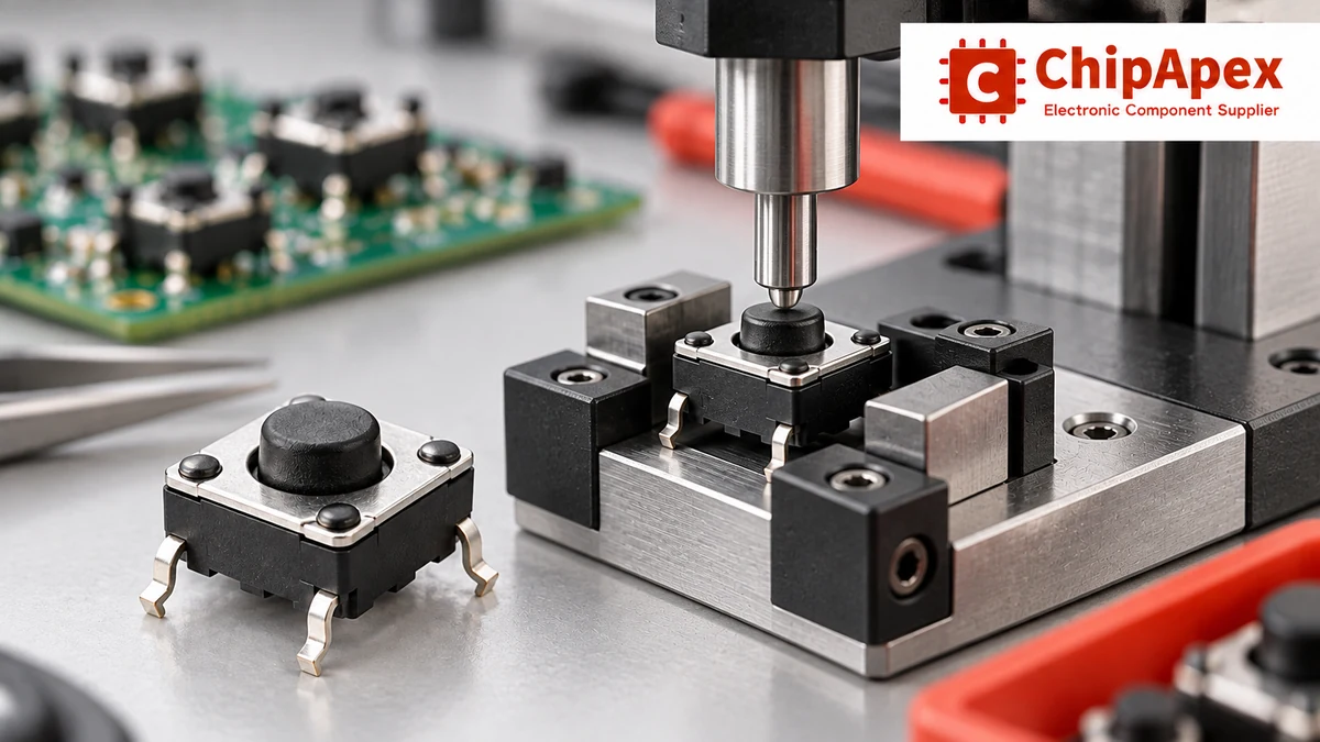
Operating force is the force required to actuate the switch under its specified test conditions. Datasheets may use newtons or gram-force. One gram-force is approximately 0.00980665 N, so a nominal 160 gf corresponds to about 1.57 N.
Two switches with that nominal force can feel different. The peak force, force drop after the snap, return behavior, travel and keycap geometry all influence the experience. A larger button, a flexible overlay or an off-axis press can further change the force perceived by the user.
| Parameter | What it describes | Why it affects the finished interface |
|---|---|---|
| Operating force | Force needed to reach actuation under stated conditions | Influences deliberate input, fatigue and accidental presses |
| Release behavior | Force and position as the mechanism returns | Affects reset and response during repeated operation |
| Force tolerance | Permitted spread between parts | Can make neighboring buttons feel inconsistent |
| Force-displacement profile | Force change through the stroke | Influences the apparent sharpness of the click |
Click ratio is sometimes defined from the force drop after the peak. Definitions and measurement methods should be checked before comparing values. Sound level is another characteristic: audible feedback and tactile feedback are related but do not have to be equally strong.
For a frequently used control, compare samples at the intended pressing rate and with representative users. A higher operating force can reduce unintended operation in one design while making another tiring. The appropriate value follows the product’s interaction requirements.
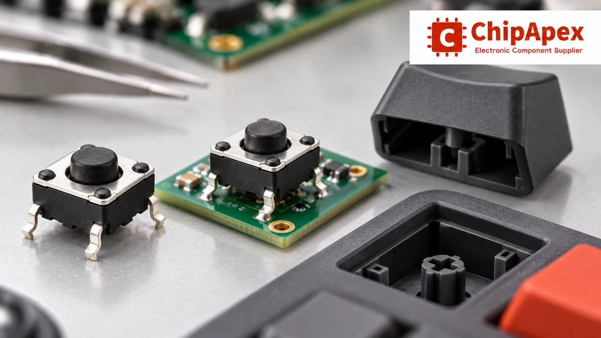
Travel is the actuator displacement during operation. Actuator height locates the pressing surface relative to a stated reference, often the PCB or switch body. Neither measurement alone determines the finished button travel.
Build the tolerance stack from the PCB position to the keycap. Include solder seating, switch height, enclosure dimensions, membrane thickness and any pivot or guide. At one tolerance extreme, the cap must still operate the switch reliably. At the other, it must not preload the switch or drive it beyond its permitted stroke.
Provide a suitable stop in the button structure where needed. Repeatedly using the switch dome as the sole mechanical end stop can apply excessive force after electrical operation. Keep the force aligned with the intended direction; side loading and off-center operation can damage the mechanism or alter its feel.
The tactile switch handling precautions explain why excessive force and angled operation affect reliability. Use the exact part’s dimensional and force limits when designing the enclosure mechanism.
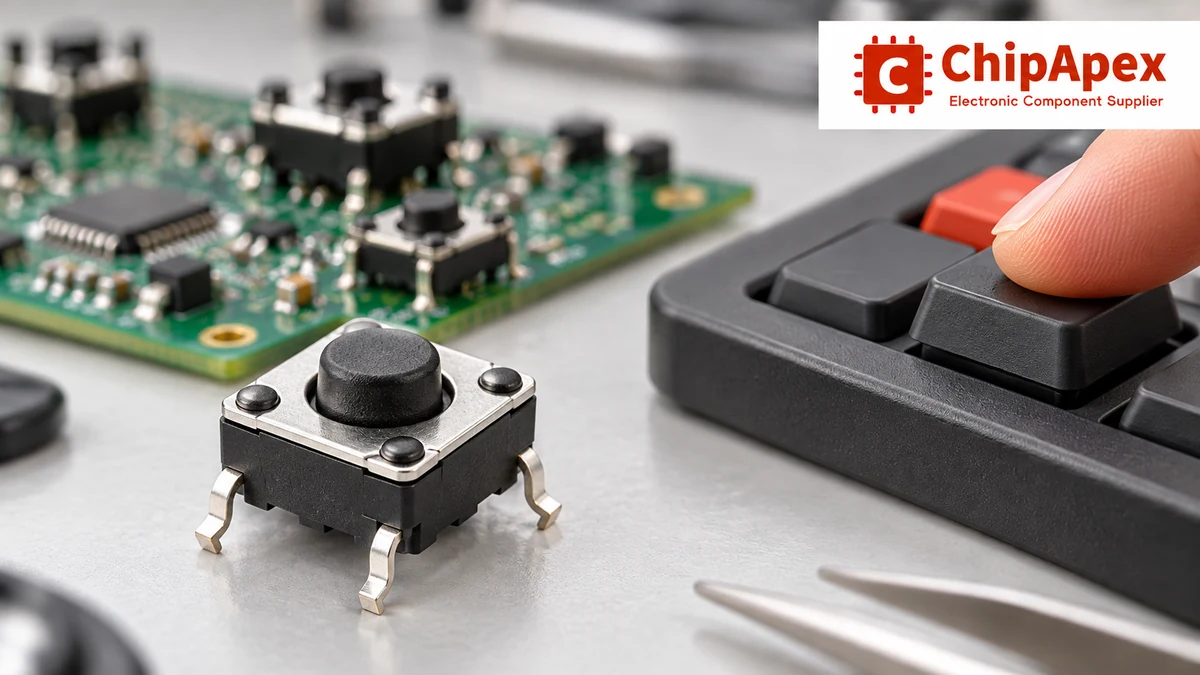
A common four-terminal tact switch contains two internally connected terminal pairs. Pressing connects the two pairs. The extra terminals can improve mechanical stability; they do not necessarily represent two independently switched circuits.
Check the actual internal diagram. Physical pin arrangement varies, and some switches include a separate grounding terminal or illumination connections. Confirm which pads are common before designing the PCB or diagnosing an input that appears permanently closed.
Two parts described as “6 × 6 mm” can have different pin spacing, body height, actuator dimensions and mounting features. Through-hole, gull-wing, J-lead, reverse-mount and right-angle variants need their own drawings. Use the recommended land pattern and verify placement orientation against the assembled enclosure.
For a maintained configuration setting, slide switches may be more suitable than a momentary tact input. Choose the circuit behavior first, then compare the mechanical interface and assembly process.
Tact switches are commonly used at signal levels. Their voltage and current ratings should not be treated as permission to switch motors, heaters or mains circuits. The rated conditions apply to the exact contact construction and specified load.
Also check the minimum applicable load where one is specified. A low-power GPIO input can present a different contact requirement from the load used in an endurance test. Contact material and plating affect suitability at very low currents.
Initial contact resistance is a specified starting characteristic. End-of-life resistance, intermittent contact and bounce behavior can matter more to a marginal input circuit. Use a defined pull-up or pull-down, valid logic thresholds and a suitable noise margin rather than assuming an open input will stay in a known state.
For a separate maintained operator control, compare toggle switch options against the required function. That change affects the electrical architecture and user interaction, so it should be treated as a design choice rather than a direct substitute.
Mechanical contacts can make and break several times during one operation. A fast digital input can interpret these transitions as multiple button events. The click the user feels does not guarantee a single clean electrical edge.
Software debouncing commonly accepts a new state only after it remains stable for a defined interval. Hardware approaches can use a suitable input-conditioning circuit. An RC network changes edge speed, so check the receiving input’s thresholds, hysteresis and rise/fall-time limits; a slow edge into an unsuitable CMOS input can create another problem.
There is no universal debounce time for every tact switch. Use the device’s bounce information and measure representative samples, including release. Check repeated presses, long holds, startup states and noise conditions. Set the response time to balance reliable event detection with the product’s responsiveness requirements.
This switch debounce application brief describes the mismatch between mechanical contact transitions and fast logic inputs. For a user interface with multiple buttons, define how the firmware handles overlapping presses and release events as well.
An endurance figure is a result under specified operating force, load, rate and environmental conditions. It is not a guarantee that every installed assembly will last for the same number of user presses.
Different operating-force variants in one family can have different life ratings. Mechanical and electrical endurance can also differ. Compare the exact variant and load conditions, including any minimum signal requirement, rather than choosing the largest cycle count from the family description.
For an arithmetic planning example, 100 operations per day for five years totals 182,500 operations before any design margin. This estimates intended usage, not field life. Accidental repeated presses, mechanical overload, contamination and contact degradation can change the real result.
Validate end-of-test function and feel in the assembly. The acceptance criterion should cover reliable input detection, return action, force change and any unacceptable sticking or double-trigger behavior, rather than only whether a continuity meter still responds.
An unsealed switch can be unsuitable in dust or liquid exposure. A component IP rating applies to stated test and mounting conditions, and may exclude terminals. It does not establish the complete product’s protection rating or compatibility with cleaning chemicals.
Process sealing also requires care. A part described as sealed is not automatically compatible with every washing or ultrasonic-cleaning process. Confirm allowable soldering temperatures, dwell times, reflow cycles, flux and cleaning methods for the exact variant.
Do not operate the switch while the assembly is still hot from soldering unless its instructions permit it. Check storage conditions and packaging controls where humidity or corrosive gases could affect contacts and terminals. A protective overlay can help with service exposure, but its force and travel must be included in the mechanical evaluation.
Specify footprint, actuation direction, body and actuator height, operating force with tolerance, travel, contact arrangement, electrical load, environmental protection and endurance conditions. Include a cap or enclosure drawing where the switch operates through another part.
Ask that alternative quotations identify differences explicitly. A pin-compatible switch with a taller actuator or a different force curve can change the user’s experience and mechanical loading. Request samples before approving such a substitution for production.
Most compact PCB tact switches are momentary: they change state while pressed and return when released. A controller can use that input to toggle a stored ON/OFF state, but the switch does not physically latch. Check the contact function because specialized constructions and other tactile-feeling switch families exist.
Many use two internally connected terminal pairs. Pressing joins the pairs, and the additional solder joints support mounting stability. Confirm the internal diagram because terminal layouts vary and some designs add a ground or lamp connection. Four pins alone do not establish a DPST circuit.
The specification refers to gram-force, a unit of force, rather than mass. A nominal 160 gf is approximately 1.57 N. The datasheet’s tolerance and test method also matter. Perceived force in the final product can change with the keycap, membrane and pressing position.
No. Click feel depends on the force-displacement behavior and mechanical assembly. Endurance must be checked for the exact switch variant under the stated test conditions. A higher-force variant can have a different cycle rating, so compare the actual ratings instead of using feel as a durability indicator.
Sealing and contact bounce address different issues. A sealed mechanical contact can still produce several transitions during operation. Use the manufacturer’s bounce information and validate the input circuit or firmware with representative switches. Check release transitions as well as button presses.
No. Compare pin spacing, circuit, height, force, travel, rated load, minimum applicable load and assembly requirements. A similar body outline can conceal a different actuator height or terminal arrangement. Verify the replacement in the actual PCB and enclosure before approving it.
Send ChipApex the approved part number or detailed switch specification, required quantity and delivery schedule. Include the actuator-height tolerance and mechanical drawing when evaluating alternatives. Request exact variant documentation and samples for the finished interface before committing to a production substitution.
Select power transformers by input frequency, secondary VA, rectifier load, isolation, regulation and inrush. Build a clearer specification for your next RFQ.
View details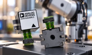
An inertial measurement unit (IMU) measures motion using an accelerometer and a gyroscope in one device or module. The accelerometer senses specific force, including the effect of gravity; the gyroscope senses angular rate. Software can combine th...
View details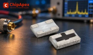
Understand RF attenuator dB values, fixed and programmable types, impedance, power limits and noise tradeoffs before choosing parts for an RF signal path.
View details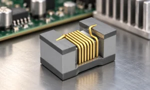
An inductor is approximately linear only over a specified operating range. In the ideal model, its inductance stays constant and voltage equals inductance times the rate of current change. A real magnetic core can approach saturation as current ri...
View details
The activity of extra discounts on wholesale prices is in full swing…
Please fill in your contact information and we will send you the latest wholesale price list.

