 ChipApex | Global Electronic Components Supplier

SEARCH
Search Product
Search Post
— IC芯片 | 连接器 | 传感器 | 被动器件 —
Search productSearch post
— IC芯片 | 连接器 | 传感器 | 被动器件 —
The trend of science and technology is changing rapidly.
A DC-DC converter changes one DC voltage into another using a switching power stage. Selection starts with the full input range and required output, then accounts for load transients, isolation, noise and heat. The nominal voltage and current on a product listing are only the beginning of the design check.
Use the lowest and highest voltage that can reach the converter during normal operation. A battery voltage changes with charge and load. An industrial bus can sag during startup or rise when other equipment changes state. Cable resistance and protection components also reduce the voltage available at the board.
Keep normal operating conditions separate from transients and absolute maximum ratings. A converter's absolute maximum input rating is not a recommended continuous operating point. The input filter, suppressor and converter must handle the expected events as a system.
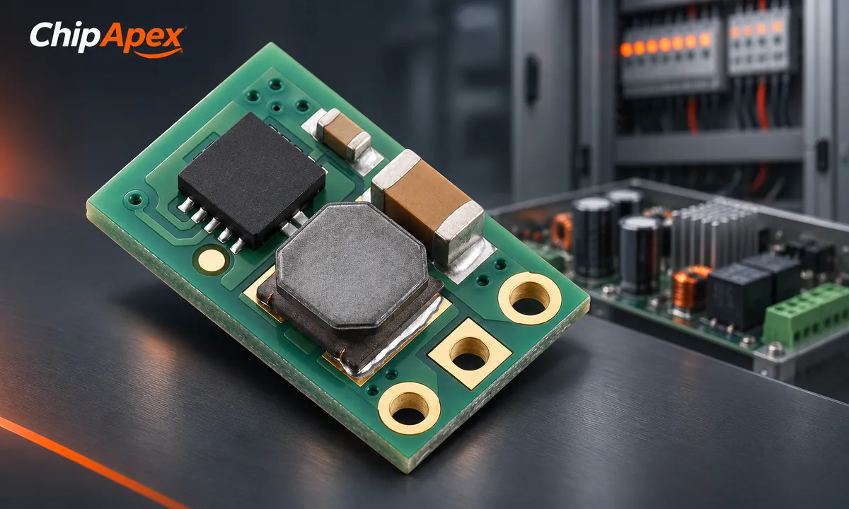
Before browsing a dc dc converter, specify continuous current, peak current, peak duration and startup load. Include output tolerance and allowable ripple. A motor, processor and precision analog circuit can impose very different demands at the same nominal voltage.
| Requirement | Common starting point | Practical constraint |
|---|---|---|
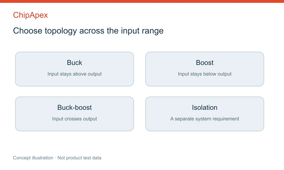
| Input stays above output | Buck | Minimum on-time, dropout behavior and duty-cycle limits |
| Input stays below output | Boost | Input current can greatly exceed output current |
| Input crosses the output voltage | Buck-boost | Efficiency and transitions across operating regions |
| Negative rail from a positive input | Inverting topology | Ground references and component voltage stress |
| Electrical separation of input and output | Isolated converter | Working voltage, barrier requirements and parasitic coupling |
A module usually integrates more of the power stage than a regulator IC, but the external component requirements vary. A controller generally needs external power switches; a converter IC often integrates switches. Read the recommended circuit rather than assuming that similar product names mean identical integration.
The TI switching-regulator overview separates the main topology families. Within each family, select for the full input and load range rather than peak efficiency at a single point.
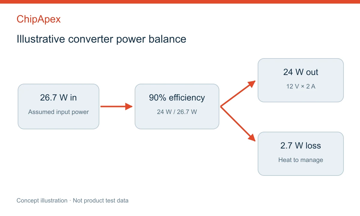
Consider a hypothetical 12 V output supplying 2 A: output power is 24 W. At an assumed efficiency of 90%, input power is about 26.7 W and converter loss is about 2.7 W. If the input is 9 V, average input current is approximately 3.0 A. These are illustrative calculations, not specifications for a ChipApex product.
The source, connectors, protection and PCB traces must support that input current. A boost converter's switch current limit is not the same as the current it can continuously deliver at the output. Inductor ripple and peak currents also matter.
Read efficiency curves at the actual input voltage and load. Then check thermal derating under conditions close to the enclosure, copper area and airflow in the application. A module tested in moving air may deliver less power inside a sealed box. Thermal shutdown is a protection mechanism, not a normal operating strategy.
Isolation can separate grounds, limit certain current paths or provide part of a safety barrier. Those are different requirements. A short-duration isolation test voltage does not by itself establish continuous working voltage, reinforced insulation or suitability for a particular installation.
Check the exact product's working-voltage ratings, creepage, clearance, isolation capacitance and relevant approvals. Transformer isolation still permits capacitive coupling at higher frequencies. Sensitive measurements may need additional filtering and layout control.
Also distinguish regulated and unregulated isolated modules. An unregulated output can change with input voltage and load; a post-regulator may be needed. The DCP01 module documentation is one example of why startup, loading and recommended capacitance must be read in the individual datasheet rather than inferred from the word “isolated.”
Ripple is the repeated variation around the output voltage. A load transient is the temporary response when the load changes. A converter with low ripple can still have a large transient dip if the control loop, output capacitor or distribution path does not meet the load requirement.
Probe technique can make switching noise look worse than it is. Use the measurement arrangement and bandwidth specified in the datasheet, with short connections. Long ground leads pick up magnetic fields and can introduce ringing into the displayed waveform.
For discrete designs, choose inductors for saturation behavior, RMS heating, DCR and core loss at the operating frequency. Capacitor capacitance may fall with DC bias. Copying a nominal value without checking the component technology can change the result substantially.
A ferrite bead can help with some high-frequency supply noise, but its impedance changes with frequency and bias. Added filtering can also interact with the converter or create resonance. Verify the circuit after adding a filter instead of treating the bead as a universal fix.
Enable thresholds, undervoltage lockout, soft start and output discharge affect how the system powers up. A heavy capacitive load may prevent startup under a current-limited soft-start scheme. A pre-biased output or another supply connected to the same rail may require specific reverse-current behavior.
Protection can take the form of current limiting, hiccup restart or shutdown. Each response affects the system differently. Confirm how a short circuit clears, whether the output restarts automatically and whether downstream circuitry tolerates repeated startup attempts.
A low dropout regulator circuit can provide a useful post-regulated rail when voltage headroom and dissipation allow it. It cannot remove arbitrary ripple at every frequency; check PSRR at the disturbance frequency and at the intended load and headroom.
A conventional buck stage steps down voltage. If the input can fall below the required output, evaluate a boost or buck-boost solution as appropriate. Include dropout and duty-cycle limitations, because an input only slightly above the output may still be insufficient under load.
No. Both isolated and nonisolated modules exist. Check the circuit description and isolation specifications. A module's shape, enclosure or number of pins does not establish the presence of an isolation barrier or its suitability for a safety requirement.
Possible causes include insufficient input power, cable drop, current limiting, thermal derating or poor transient response. Measure voltage at the converter input and output while applying the load. Compare the observed timing with the datasheet's protection and startup behavior.
There is no universal percentage that covers every application. Use continuous and transient loads, ambient temperature, airflow, expected life and the manufacturer's derating curves. A large nameplate margin does not compensate for unsuitable thermal conditions or an unsupported transient load.
An LDO can be attractive when the voltage difference and load current are small, or when its simplicity and noise performance fit the rail. Approximate dissipation as voltage drop multiplied by load current, with additional quiescent losses. For a large drop or higher current, a switching stage often reduces heat.
Provide ChipApex with the full input range, output voltage, continuous and peak load, isolation requirement, temperature, available space and quantity. Include allowable ripple and any startup or sequencing restrictions so candidate parts can be checked against the actual circuit.
Stop guessing which Op-Amp to use. We break down GBWP, Slew Rate, and Offset Voltage with real engineering insights. Find the right parts like NE5532DR & LM358DR at ChipApex.
View details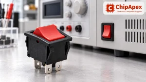
Choose a rocker switch by AC/DC ratings, contact arrangement, illumination, panel fit and sealing. Get practical checks for engineering and component sourcing.
View details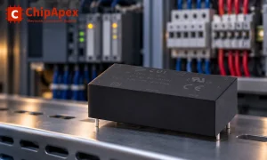
Choose an AC to DC converter by input range, output demand, isolation, efficiency and thermal derating. Compare architectures and check installation needs.
View details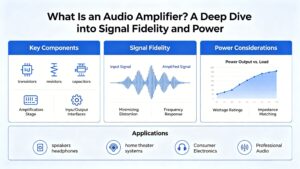
Learn how audio amplifiers work, compare Class AB vs. Class D, and discover key metrics (THD+N, SNR). Source authentic TI/ST audio ICs at ChipApex for your design.
View details
The activity of extra discounts on wholesale prices is in full swing…
Please fill in your contact information and we will send you the latest wholesale price list.

