 ChipApex | Global Electronic Components Supplier

SEARCH
Search Product
Search Post
— IC芯片 | 连接器 | 传感器 | 被动器件 —
Search productSearch post
— IC芯片 | 连接器 | 传感器 | 被动器件 —
The trend of science and technology is changing rapidly.
An analog-to-digital converter turns an analog input into a sequence of digital codes. Choosing an ADC means matching its input range, noise, bandwidth and timing to the signal you need to measure. More bits can make the code steps smaller, but they do not automatically make the complete measurement more accurate.
Write down the signal's minimum and maximum voltage, useful frequency range, source impedance and required measurement uncertainty. Include abnormal conditions, such as a disconnected sensor or an input present before the board powers up. These conditions influence protection and input drive as much as the nominal signal does.
A slowly changing temperature signal and a vibration waveform can have similar voltage ranges yet need different converters. Temperature measurement may favor low noise and rejection of line-frequency interference. Vibration analysis needs enough bandwidth, predictable filtering and timing to preserve the waveform. Browse an adc converter by those requirements before comparing package sizes.
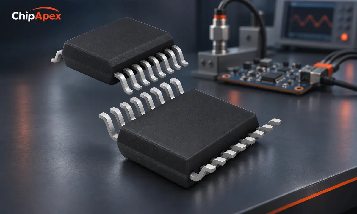
Specify whether the requirement is absolute accuracy, repeatability or detection of a small change. A system can repeat a reading closely while retaining a gain error. Calibration may remove some systematic errors, but it cannot recover an input that clips or remove every noise source.
For an ideal N-bit converter, the nominal code width is the full-scale input span divided by 2^N. A hypothetical 12-bit ADC covering 0 to 4.096 V therefore has a nominal 1 mV code width. This calculation describes quantization. It excludes reference error, offset, gain error, nonlinearity and noise.
| Specification | What it helps establish | What to check with it |
|---|---|---|
| Resolution | Number of available codes | Actual input span and coding format |
| Offset and gain error | Static transfer-function error | Calibration and temperature drift |
| INL and DNL | Departure from an ideal transfer curve | Definition, limits and missing-code behavior |
| SNR and SINAD | Dynamic performance | Input frequency, amplitude and sample rate |
| ENOB | Effective dynamic resolution derived from SINAD | The test conditions, not just the headline value |
| Input-referred noise | Small-signal measurement floor | Filter, gain, bandwidth and output rate |
ENOB is useful when comparing dynamic measurements under similar conditions. Noise-free resolution is often more useful for a near-DC sensor. Neither should be substituted for a guaranteed total accuracy specification. The ADC architecture discussion from Analog Devices explains why the conversion method and application must be considered together.
SAR converters usually suit measurements that need a defined sampling instant and short conversion latency. They are common in control loops and multiplexed systems. Their switched-capacitor inputs can demand a driver that settles quickly during the acquisition interval.
Delta-sigma converters combine oversampling with digital filtering. Many are useful for precise, lower-bandwidth sensor measurements; other designs support much wider bandwidths. The output data rate, filter passband and settling delay must be read separately. After switching channels or changing gain, some devices need time before their output represents only the new input.
Pipeline and flash architectures address different high-speed requirements, with tradeoffs in latency, power and complexity. Integrating converters remain useful for some slow precision measurements. Architecture names narrow the search; the actual specifications decide whether a particular part fits.
An integrated analog front end can simplify a sensor interface by including a PGA, multiplexer or excitation circuitry. Check which functions are present and whether their limits match the sensor.
The ADC input is not always a steady, high resistance. A sampling network may draw brief charging currents. A sensor that drives a multimeter correctly can produce errors when connected directly to such an input.
The driver amplifier, series resistor, capacitor and ADC input must settle together. Excessive series resistance slows settling; excessive capacitance can affect amplifier stability. For differential inputs, both the differential signal range and the allowed common-mode voltage matter. A differential input does not imply isolation or unlimited voltage on either pin.
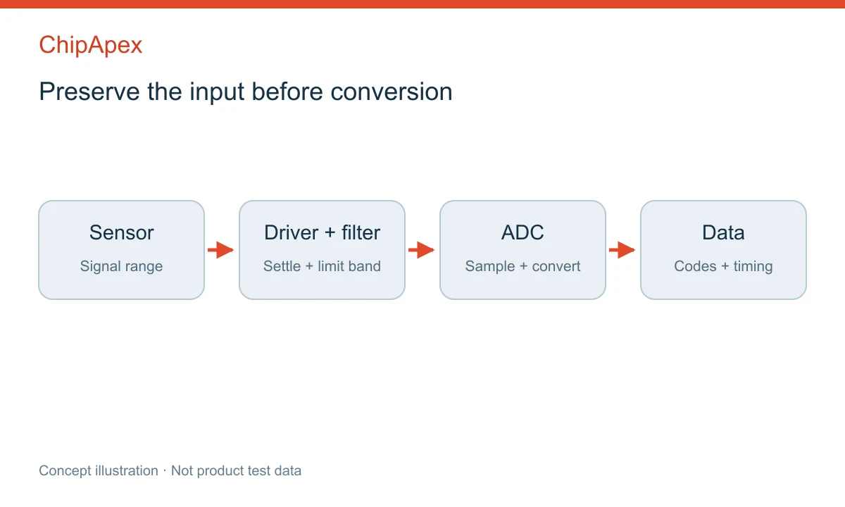
An instrumentation op amp may provide gain or common-mode rejection ahead of the converter, but it still needs suitable output swing, bandwidth and settling behavior. Use the converter's recommended driver circuits as a starting point. SAR input-drive guidance also explains why the first result after startup or a channel change needs attention.
For a baseband signal, sampling must exceed twice the highest frequency that remains at the ADC input. A real anti-alias filter has a transition band, so designing exactly at twice the wanted bandwidth usually leaves no practical filtering margin. Choose the filter and sample rate together.
Digital filtering after conversion cannot separate a wanted signal from interference that has already aliased onto it. With delta-sigma devices, consult both the analog input requirements and the digital filter response. Output rate alone does not describe the full signal bandwidth.
Also distinguish aggregate throughput from samples per channel. A hypothetical eight-channel multiplexed ADC operating at 80 kS/s offers at most 10 kS/s per channel under an equal schedule, before accounting for settling or other overhead. The channels are sampled at different times. Applications comparing phase or instantaneous power may need simultaneous sampling.
The voltage reference sets the conversion scale in many ADCs. Its initial accuracy, drift, noise and ability to handle dynamic loading affect the result. A precise reference IC connected through a poor layout can still give a noisy or unstable scale.
Ratiometric measurement is useful when a sensor output and ADC reference share the same excitation relationship. It can reduce sensitivity to excitation variation, but requires a suitable circuit and does not cancel every sensor or wiring error.
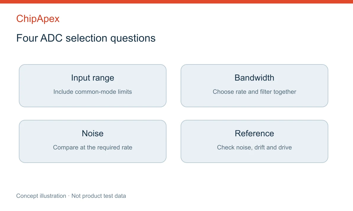
Check analog and digital supply ranges, reference startup, decoupling and power sequencing. Then confirm that the host can read the converter at the intended rate. SPI clock limits, data framing, conversion-ready timing and logic levels can make an otherwise suitable converter inconvenient to use. An interface-speed calculation should include command and framing overhead.
The output word can contain 24 bits while noise and errors reduce useful measurement resolution. Check input-referred noise, linearity, gain and offset drift, reference performance and the selected filter. The complete sensor chain determines accuracy; the output word length only states how the result is encoded.
A faster device can create more data and demand a faster driver, interface and processor. It may also use more power. Select enough speed for the signal and filtering requirements, then compare noise and power at the operating mode you will actually use.
Averaging can reduce some uncorrelated noise when the signal is sufficiently stable. It costs response time and does not automatically remove offset, gain error, drift or interference synchronized to sampling. Evaluate the error source before relying on a larger averaging window.
Sometimes. Confirm the sensor output range, impedance and settling capability against the ADC's input circuit. Protection, level shifting, gain or buffering may still be needed. A converter with an integrated PGA or buffer can simplify the circuit, but its input common-mode and bandwidth limits still apply.
Use it when the time relationship between channels matters enough that sequential sampling introduces unacceptable error. Examples include phase comparison and correlated transient measurements. A multiplexed ADC can be sufficient for slowly varying channels when the scan delay is known and acceptable.
Send ChipApex the input span, channel count, useful bandwidth, accuracy target, interface, supply rails, package and required quantity. Include an existing part number or schematic constraints when available so the enquiry can focus on electrically suitable candidates.
Choose LED drivers by current, string voltage, dimming and thermal limits. Understand constant-current operation and the checks needed for your load.
View details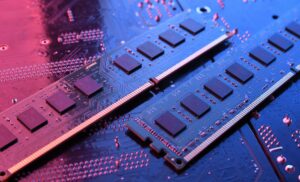
Discover what DRAM is, how it works, its types, and why choosing authentic, RoHS-compliant DRAM chips matters. Source reliable DRAM from ChipApex—global supplier with full traceability.
View details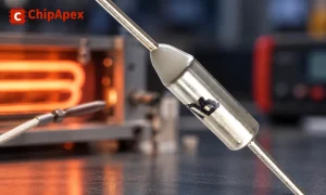
Understand thermal fuse operation, Tf, Th and Tm, electrical ratings and mounting. Check temperature limits and replacement requirements for your design.
View details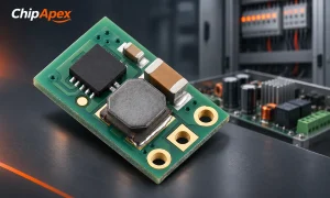
Select a DC-DC converter by input range, topology, isolation and temperature. Compare ripple, efficiency and load limits before choosing a component.
View details
The activity of extra discounts on wholesale prices is in full swing…
Please fill in your contact information and we will send you the latest wholesale price list.

