 ChipApex | Global Electronic Components Supplier

SEARCH
Search Product
Search Post
— IC芯片 | 连接器 | 传感器 | 被动器件 —
Search productSearch post
— IC芯片 | 连接器 | 传感器 | 被动器件 —
The trend of science and technology is changing rapidly.
LED drivers regulate the electrical power delivered to an LED load. For a bare LED string, current usually determines the operating point. For a lighting assembly that already contains current-limiting circuitry, a specified constant-voltage supply may be appropriate. Matching only the wattage can leave the LEDs overdriven, dim, unstable or unable to start.
Begin with the load's electrical requirements and the available input supply. Then check the driver's output range, dimming behavior, thermal limits and protection functions. This article focuses on driver selection and board-level design rather than installation of mains wiring.
A constant-current driver adjusts its output voltage to maintain a target current within a defined operating range. A constant-voltage supply maintains a voltage; the load must contain a suitable way to control current. These two arrangements are not interchangeable merely because their labels show the same power rating.
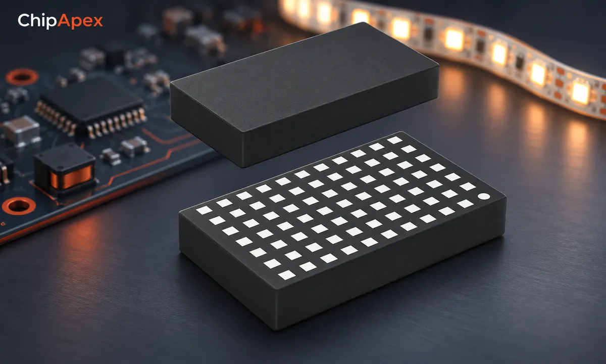
Catalog-based IC illustration; the scene does not represent a complete certified lighting supply.
Check the LED module's documentation before choosing among led drivers. A bare high-power LED string and a resistor-limited strip can require different supplies. Some modules integrate their own driver, while others need an external constant-current source. The connector shape does not tell you which arrangement is present.
For series-connected LEDs, add the forward-voltage requirements at the intended operating current. Include device tolerance and temperature effects. The driver must have enough compliance voltage to regulate current throughout that range, including any required headroom.
As an illustrative example, eight LEDs with a forward-voltage range of 2.8 to 3.4 V each produce a string range of 22.4 to 27.2 V. At 350 mA, LED electrical power spans roughly 7.8 to 9.5 W. These assumed values do not describe a specific product, and driver losses add to input power.
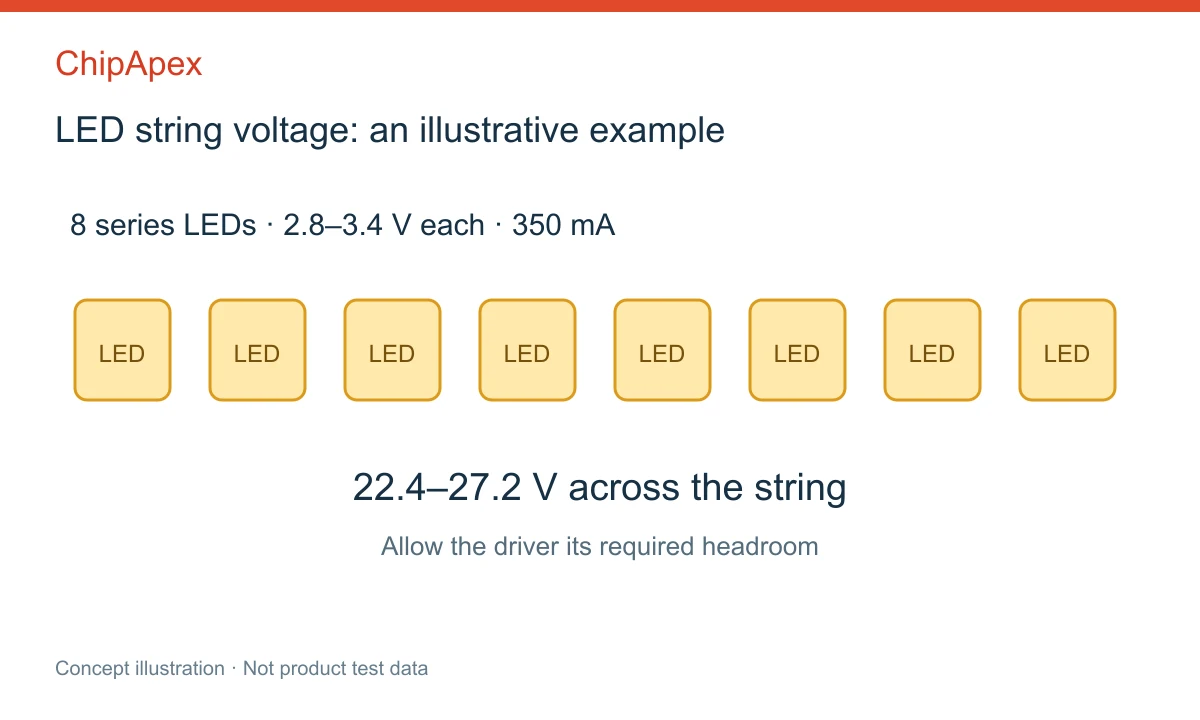
Example only. Use actual LED data at the intended current and temperature.
A buck driver needs sufficient input voltage above its output requirement. A boost driver raises voltage and has its own startup and fault-path considerations. A buck-boost arrangement may suit an input that crosses the required string voltage. The topology must support the entire operating range, not only the nominal supply value.
For example, the TI LM3402 documentation describes a buck LED driver and the associated current-regulation architecture. Its behavior is an example of one device family, not a specification shared by all LED drivers.
PWM dimming switches LED current on and off while changing duty cycle. Analog dimming changes the regulated current level. Some drivers support both. Their useful dimming range depends on minimum pulse width, settling time, current accuracy and the implementation around the IC.
| Dimming method | Useful characteristic | Design check |
|---|---|---|
| PWM | Controls average output through duty cycle | Pulse timing, visible artifacts, camera interaction and acoustic behavior |
| Analog | Avoids repeated full-current pulses at the dimming rate | Low-current regulation, color shift and current-setting accuracy |
| Combined | Extends control options | Smooth transitions and consistent behavior across modes |
At low brightness, a nominally high PWM resolution may be unusable if the driver cannot settle during the shortest pulse. Conversely, reducing current far below the normal operating point may change LED behavior or expose regulation limits. Test the actual light source across its intended dimming range.
Do not equate a single dimming frequency with flicker-free performance in every application. Human perception, motion and camera exposure differ. Evaluate the relevant use case, including rolling-shutter imaging when the lighting is used near cameras.
Driver losses heat the IC and surrounding components. LED junction temperature also depends on the board, heatsink, enclosure and ambient conditions. A driver that regulates correctly on an open bench may behave differently in a sealed luminaire.
Check current-sense resistor dissipation, switch losses, diode losses where applicable and magnetic-component heating. Select inductors against peak current, saturation behavior and losses at the switching frequency. A current rating based only on temperature rise may not describe saturation limits.
The thermal path through the PCB matters for exposed-pad packages. Follow layout and assembly guidance for copper area, vias and pad connection. Thermal shutdown protects the driver under certain conditions; it is not a substitute for a design that operates within its normal thermal limits.
Open-LED, short-circuit and overtemperature behavior varies by device. An open string can cause a boost stage to raise its output until a protection threshold is reached. A shorted LED changes the string voltage and may increase dissipation elsewhere. Verify both the fault response and recovery behavior.
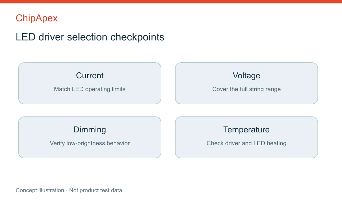
Four selection checks that should be verified on the intended load.
Keep high-current switching loops compact, and separate sensitive current-sense routing from noisy nodes. A ferrite bead may help in a suitable filter network, but adding one without understanding impedance and resonance can create a new problem. Measure the relevant conducted and radiated behavior in the assembled system.
For multichannel indicators or displays, a constant-current sink driver can serve a different role from a power converter. The TI TLC5926 documentation illustrates a multichannel current-sink architecture. Check output compliance and total package dissipation rather than assuming every device labeled LED driver converts the supply voltage.
Only if its regulation type, current setting and voltage range match the load. Extra rated power does not make an incompatible constant-current output safe for a lower-current LED string. With a compatible constant-voltage system, available supply power can exceed the load demand, but startup and protection behavior still need review.
Parallel strings may divide current unevenly because forward voltage and temperature differ. A total-current regulator does not automatically regulate each branch. Use a design with appropriate current balancing or individual regulation, and check how the circuit responds if one string disconnects or changes temperature.
Possible causes include minimum PWM pulse limits, unstable current regulation, supply interaction or an incompatible dimming interface. Measure the driver input, output current and dimming signal together. The symptom may originate in the controller or supply rather than the LED itself, so changing only the light source may not solve it.
Usually not. An IC may require external magnetic components, capacitors, resistors, switching devices and a suitable PCB layout. A finished module integrates more of the circuit but still has installation and thermal requirements. Mains-powered assemblies also need the appropriate insulation, protection and compliance design.
It stabilizes an important electrical variable, but light output also depends on LED temperature, device variation and aging. Optical requirements may therefore need thermal control, calibration or feedback. The driver's current tolerance alone does not establish the complete luminaire's brightness uniformity or long-term light output.
For ChipApex, provide input-voltage limits, series and parallel LED arrangement, forward-voltage range, target current, dimming method and ambient conditions. Include package and control-interface constraints. If the design also needs a board-level dc dc converter, specify that rail separately so its requirements are not confused with LED current regulation.
Select power transformers by input frequency, secondary VA, rectifier load, isolation, regulation and inrush. Build a clearer specification for your next RFQ.
View details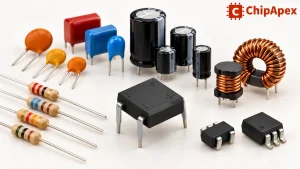
Explore electronic component types, functions, packages and datasheets. Learn selection, replacement and BOM checks before ordering parts for your PCB.
View details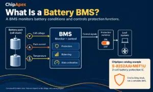
A battery BMS, or battery management system, monitors a battery and controls how it is used within defined operating limits. It measures conditions such as cell voltage, pack current and temperature. Depending on the design, it can also balance ce...
View details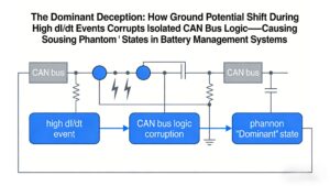
Ground potential shift during high dI/dt regen braking causes isolated CAN receivers to output false dominant states, locking EV BMS networks. Discover robust solutions like TJA1044GT/3Z + common-mode filtering validated by ChipApex.
View details
The activity of extra discounts on wholesale prices is in full swing…
Please fill in your contact information and we will send you the latest wholesale price list.

