 ChipApex | Global Electronic Components Supplier

SEARCH
Search Product
Search Post
— IC芯片 | 连接器 | 传感器 | 被动器件 —
Search productSearch post
— IC芯片 | 连接器 | 传感器 | 被动器件 —
The trend of science and technology is changing rapidly.
A load cell sensor converts force into an electrical signal. In a strain-gauge load cell, force slightly deforms an elastic element, changing the resistance of bonded gauges. A bridge circuit turns those resistance changes into a small differential voltage. The readout then converts the signal into force or, under defined conditions, weight.
Choosing a load cell requires both mechanical and electrical decisions. Capacity alone does not tell you whether a sensor will work in a platform scale, compression fixture or tension measurement. Load direction, mounting, overloads and the measurement electronics all affect the result.
Single-point, bending-beam, shear-beam, S-type and compression load cells suit different mechanical arrangements. A compact force sensor may be designed for a small contact force rather than a complete weighing platform. Confirm how force enters and leaves the sensing element before treating two products as substitutes.
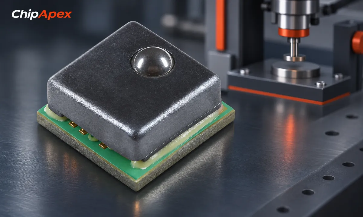
Representative catalog force sensor in an illustrative setting; not a specified load-cell installation.
When reviewing load transducers, consider the maximum expected load plus installation and handling events. Side loads, bending moments and impact can exceed the intended loading condition even when the nominal vertical load is within capacity. A mechanical overload stop may be necessary, but its geometry must not bypass the sensor during normal measurement.
Higher capacity creates additional headroom but can reduce the output change per unit of force. Select capacity against both overload requirements and the smallest useful load increment. Do not assume that a nominal safe-overload rating means the device will retain its stated measurement accuracy during overload.
Include the weight of the platform or fixture itself when calculating the operating load. Repeated loading also deserves a separate check: a sensor designed mainly for static measurement may not have the fatigue rating needed for continuous cycling. Capacity, load distribution and service conditions should be reviewed together.
Many bridge load cells specify rated output in millivolts per volt of excitation. For an illustrative 2 mV/V sensor excited at 5 V, the nominal full-scale differential output is 10 mV. At one-tenth of rated load, the ideal signal change is about 1 mV, excluding zero offset, nonlinearity and other errors.
That small differential signal may sit on a much larger common-mode voltage. An amplifier must accept both the differential range and common-mode level at the chosen supply voltage. Input offset, drift and noise can become significant compared with the load signal.
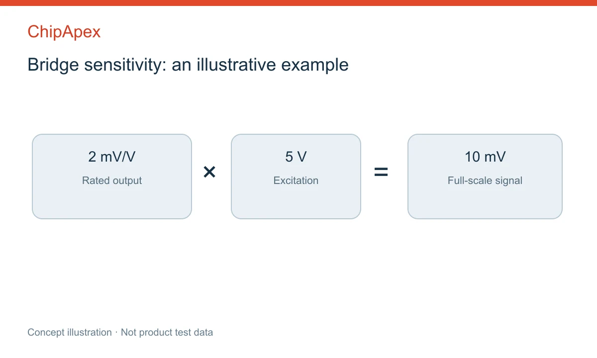
Example values explain sensitivity; they are not specifications for the pictured product.
A suitable instrumentation op amp can provide gain and reject common-mode interference, subject to its operating limits. Alternatively, some precision converters include a programmable-gain stage intended for bridge measurements. Check the permitted input range at the selected gain instead of assuming the highest gain is always usable.
A typical four-wire bridge uses two excitation connections and two signal connections. A six-wire arrangement adds sense wires so compatible electronics can monitor excitation at the bridge. This can help account for voltage drop in long excitation leads. Actual wire colors and terminal names vary by manufacturer; use the specific wiring diagram.
Shielding and grounding require a system decision. Keep low-level signal wiring away from switching power conductors and motor cables. Twisted differential signal pairs can reduce pickup, but they do not fix an input that exceeds its common-mode limits. Avoid arbitrary connections between shield, signal return and chassis.
Ratiometric measurement uses a reference related to the bridge excitation. If signal and reference scale together, some excitation variation cancels in the conversion ratio. This does not cancel every error: lead resistance, mismatched sensing points, amplifier drift and mechanical effects still matter. Texas Instruments' bridge-measurement guidance discusses practical precision measurement considerations.
A display can show many decimal places while the mechanical system drifts by a much larger amount. Assess the full error budget: zero balance, sensitivity tolerance, nonlinearity, hysteresis, creep, temperature effects, amplifier errors, converter noise and installation effects.
| Error source | What it looks like | Useful check |
|---|---|---|
| Zero offset | Nonzero reading without applied load | Zero procedure and temperature stability |
| Hysteresis | Different readings when approaching a load from above or below | Increasing and decreasing load sequence |
| Creep | Reading changes while a constant load remains applied | Defined dwell time under stable conditions |
| Temperature effects | Zero or span changes with temperature | Operating-temperature characterization |
| Mechanical interference | Reading depends on contact, cable or platform position | Inspect force path and loading geometry |
Select an adc converter using noise at the required output rate and gain. Nominal bit count is only a starting point. Filtering can stabilize the reading, but extra averaging increases response time and can conceal a short transient.
Zero calibration establishes the unloaded baseline. Span calibration relates a known applied load to the output change. Use appropriate reference loads and a procedure suited to the required uncertainty. Calibration of the bare sensor does not automatically include the effects of the installed fixture, cable, electronics and software.
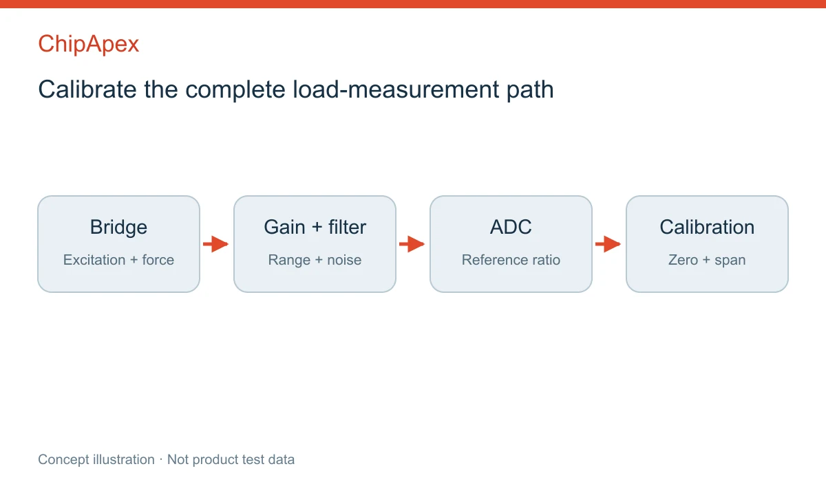
System-level calibration includes the assembled mechanical and electronic path.
Apply loads at relevant positions if off-center loading is possible. Repeat loading and unloading to reveal hysteresis and mechanical sticking. Allow the assembly to settle, and record temperature when it could affect the result. A calibration curve cannot reliably correct unstable mounting or intermittent electrical connections.
For a multi-cell platform, verify load distribution and corner behavior. The maximum load on one cell can exceed the average share when the load sits near an edge. Flintec's load-cell overview provides useful context on construction and application types.
A load cell measures force. A weighing system relates that force to mass using calibration and the relevant gravitational conditions. In many stationary applications the distinction is handled by the instrument, but acceleration, vibration and changing orientation can affect the force applied to the sensor and therefore the indicated weight.
A raw bridge output is often too small for a general-purpose microcontroller ADC to measure well without conditioning. Check excitation, differential input capability, gain, noise and common-mode range. A dedicated bridge converter or instrumentation amplifier may be appropriate. A load-cell assembly with a built-in digital interface is a different case.
It may provide useful resolution, but the number of bits does not establish system accuracy. Noise-free resolution at the selected gain and data rate matters, along with load-cell performance, temperature, mounting and calibration. Decide the required uncertainty first, then allocate an error budget across the complete measurement path.
Possible causes include load-cell creep, temperature change, mechanical settling, excitation variation and electronic drift. Check whether the change follows time, temperature or cable movement. A stable reference load and repeated controlled tests help separate mechanical behavior from electrical interference or software filtering effects.
Not automatically. Compare geometry, loading direction, rated output, excitation limits, impedance, wiring, overload behavior and environmental ratings. The replacement may also need a new calibration. Identical capacity markings do not guarantee the same sensitivity, mounting compatibility or accuracy in the existing assembly.
Send ChipApex the force range, loading direction, mounting drawing, required sensitivity, excitation voltage, cable arrangement and target measurement rate. Include the existing part number when replacing a sensor. For a new electronics design, identify the required voltage reference arrangement and converter interface so the bridge and acquisition circuit can be considered together.
Choose a rocker switch by AC/DC ratings, contact arrangement, illumination, panel fit and sealing. Get practical checks for engineering and component sourcing.
View details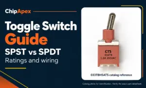
Compare SPST and SPDT toggle switches, understand AC/DC ratings, and follow wiring examples. Check contact action, mounting and parts in the ChipApex catalog.
View details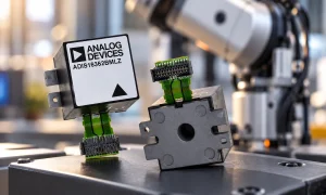
An inertial measurement unit (IMU) measures motion using an accelerometer and a gyroscope in one device or module. The accelerometer senses specific force, including the effect of gravity; the gyroscope senses angular rate. Software can combine th...
View details
Choose an ADC converter by resolution, sample rate, noise and input design. Review practical tradeoffs and prepare component requirements for ChipApex.
View details
The activity of extra discounts on wholesale prices is in full swing…
Please fill in your contact information and we will send you the latest wholesale price list.

