 ChipApex | Global Electronic Components Supplier

SEARCH
Search Product
Search Post
— IC芯片 | 连接器 | 传感器 | 被动器件 —
Search productSearch post
— IC芯片 | 连接器 | 传感器 | 被动器件 —
The trend of science and technology is changing rapidly.
A vibration sensor converts mechanical motion into an electrical signal. The useful choice depends on which motion you need to observe, its frequency and amplitude, and how the sensor attaches to the machine. A sensor that reliably detects a large impact may miss a small bearing-related signal. A sensitive sensor may clip during startup.
For condition monitoring, define the fault and measurement location before choosing a package. Motor housings, bearing supports and slow-moving structures do not present the same measurement problem. This guide focuses on sensor and signal-chain selection; a vibration reading alone does not establish a machine diagnosis.
Acceleration, velocity and displacement describe related aspects of motion. For a sinusoidal displacement of amplitude X and frequency f, velocity amplitude is 2πfX and acceleration amplitude is (2πf)²X. Frequency therefore changes how prominent the same motion appears in each measurement.
Acceleration is useful for higher-frequency content and transient events. Velocity often supports overall machinery trending within a defined band. Displacement can be useful for low-frequency motion or shaft position, depending on the sensing arrangement. Integration can convert acceleration to velocity or displacement, but low-frequency offsets and noise also accumulate. The result depends on filtering and the sensor's usable low-frequency response.
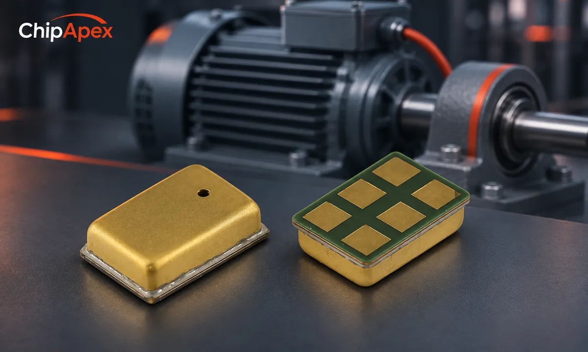
Product-based concept image; the background does not represent a tested installation.
When comparing vibration analysis sensors, specify the measured quantity, frequency band, expected peak amplitude and mounting location. Those four requirements eliminate many unsuitable candidates before price or connectivity becomes relevant.
| Technology | Typical reason to consider it | What to check |
|---|---|---|
| MEMS accelerometer | Compact sensing, low-frequency response and integrated interfaces | Noise density, bandwidth, range, axis response and power |
| Piezoelectric accelerometer | Dynamic vibration measurement, often over a wide usable band | Low-frequency cutoff, conditioning, mounting and temperature |
| Proximity sensor | Noncontact displacement relative to a target | Target material, gap, linear range and installation geometry |
| Vibration switch | Simple threshold event detection | Threshold repeatability, filtering and whether raw waveform data are available |
These are broad categories, not performance guarantees. A low-noise industrial MEMS device and a low-cost motion detector can have very different useful bandwidths. Likewise, piezoelectric systems need a compatible charge or integrated-electronics signal interface. See Analog Devices' predictive-maintenance sensor comparison for the tradeoffs between sensing technologies.
Choose single-axis or multiple-axis accelerometers according to the motion and accessible mounting surfaces. Three axes provide more information, but they also increase acquisition, storage and analysis requirements. A poorly mounted three-axis sensor does not compensate for an unsuitable location.
The measurement band must include the features you intend to trend. Rotational speed can help identify relevant frequencies, but bearing and gear analysis may require information well above the fundamental rotation frequency. The highest advertised frequency is not necessarily the flat, calibrated operating band.
Noise density, usually expressed per square root of bandwidth, indicates how broadband noise grows as the measurement band widens. For approximately white noise, integrated RMS noise scales with the square root of the effective noise bandwidth. Filter shape matters, so a simple bandwidth multiplication is only an estimate.
At the other end of the range, allow for startup, shocks and occasional overloads. A waveform that clips can generate misleading spectral content. Check recovery after overload as well as the nominal full-scale range. Record both peak and RMS values when assessing headroom; they are not interchangeable without a waveform assumption.
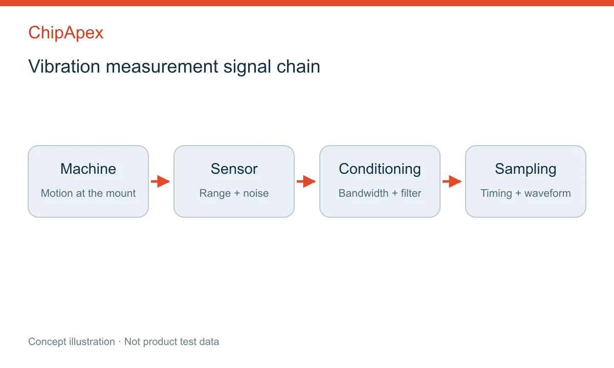
Conceptual signal chain. Each stage must preserve the frequency band of interest.
For an analog-output sensor, match the output impedance and signal range to the analog front end. Include anti-alias filtering before conversion. For digital-output devices, verify internal filtering, output data rate and the timing of samples rather than assuming the bus speed defines the measurement bandwidth.
The mechanical path between the machine and sensing element is part of the measurement. A flexible bracket, thick adhesive layer or enclosure resonance can attenuate or amplify selected frequencies. Keep mounting geometry repeatable when comparing data over time or across machines.
Follow the sensor manufacturer's mounting instructions, including surface preparation and fastening limits. A convenient magnetic or adhesive mount may have a different useful frequency response from a rigid stud mount. Cable movement can also introduce artifacts in some systems, so provide strain relief without loading the sensor mechanically.
Enclosures need their own review. Water resistance, connector retention and chemical compatibility matter in a factory, but a mechanically compliant housing can compromise the signal. Analog Devices' enclosure design discussion explains why mechanical resonance belongs in the sensor-system design process.
Record measurements at a known operating state: speed, load, temperature, sensor position and acquisition settings. A change in process conditions can change the vibration spectrum without a new mechanical defect. Trending is more useful when those conditions are stored alongside the waveform.
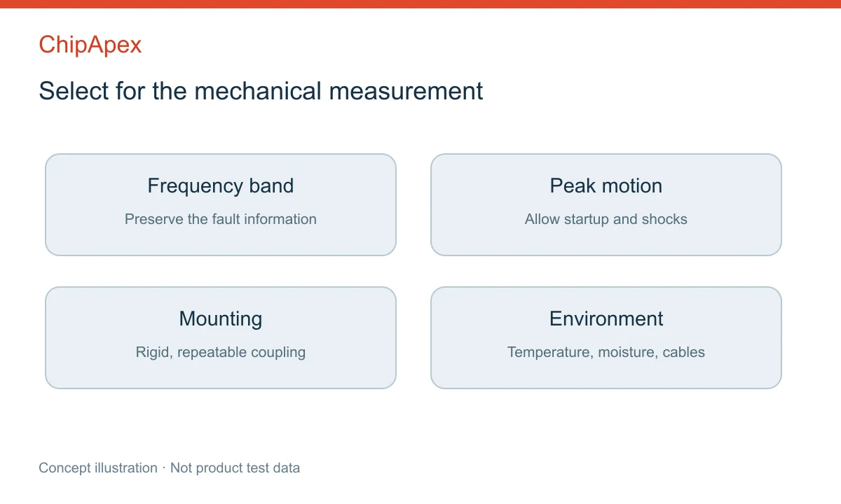
Selection checkpoints, not universal alarm limits.
Use consistent frequency bands and processing settings for comparisons. If you change the sensor, mount or filter, collect a new comparison dataset before interpreting a shifted baseline as degradation. Alarm thresholds should follow the machine's requirements and applicable assessment methods; a single generic threshold cannot cover all equipment.
For intermittent faults, decide whether continuous capture, triggered bursts or scheduled snapshots are appropriate. Battery life and wireless bandwidth can limit raw waveform collection. A transmitted summary value may hide details needed for diagnosis, so document exactly what the sensor or gateway calculates.
An accelerometer is one type of vibration sensor. Other devices measure displacement, velocity or threshold events. The terms overlap in product catalogs, so check the actual measured quantity, frequency response and output. A motion-detection accelerometer may not offer the noise performance or bandwidth required for machinery analysis.
It can if its low-frequency response and noise are suitable. Some MEMS accelerometers can respond down to DC, while piezoelectric measurement chains have a low-frequency cutoff. Displacement measurements may be useful for slow motion. The mechanical installation and filtering still determine the usable system response.
No. It can preserve a wider band or support processing, but it does not remove sensor noise, mounting errors or aliasing already introduced before sampling. Select a rate and filter together. Also check storage, power and communication requirements when increasing the number of samples.
No. Location and mechanical coupling affect which motion reaches the sensor. Select a structurally suitable point relevant to the component being monitored, follow mounting guidance and keep the location consistent. A thin cover or flexible bracket can produce readings dominated by local resonance rather than the intended machine motion.
Vibration can provide useful evidence, but interpretation depends on operating conditions, frequency content and machine geometry. Temperature, current, acoustic data and inspection may add context. Avoid treating an unexplained increase in overall vibration as proof of one specific defect without further analysis.
For a ChipApex component inquiry, include the frequency band, peak acceleration or other measured quantity, number of axes, output interface, mounting constraints and operating environment. If the design uses an external adc converter, include its input range and sample timing. This helps narrow the inquiry to components that fit the measurement rather than simply sharing a sensor label.
Choose logic inverter ICs by thresholds, supply, output drive and delay. Compare standard and Schmitt-trigger inputs, power sequencing and replacement checks.
View details
Compare RC, crystal and MEMS oscillator circuits. Check ppm, jitter, load capacitance, startup margin and output compatibility before choosing a clock source.
View details
A pressure transducer turns pressure into an electrical signal that a controller can read. Inside the device, a sensing element responds to pressure; the electronics then provide a specified voltage, current, or digital output. The output format m...
View details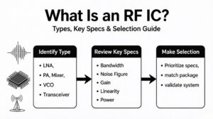
Learn what an RF IC is, how LNAs, PAs, mixers, attenuators and transceivers differ, and how to choose the right RF component. Includes verified part numbers and layout tips.
View details
The activity of extra discounts on wholesale prices is in full swing…
Please fill in your contact information and we will send you the latest wholesale price list.

