 ChipApex | Global Electronic Components Supplier

SEARCH
Search Product
Search Post
— IC芯片 | 连接器 | 传感器 | 被动器件 —
Search productSearch post
— IC芯片 | 连接器 | 传感器 | 被动器件 —
The trend of science and technology is changing rapidly.
Electronic components are the individual devices used to control, store, convert, sense, connect or protect electrical signals and energy. Common examples include resistors, capacitors, diodes, transistors, integrated circuits and connectors. Choosing a component requires matching its electrical behavior, package and operating conditions to the circuit, then confirming the exact orderable part.
A parts list becomes useful when it explains what each device does and which specifications affect the design. This guide connects the main component families with practical checks for PCB design, replacement and purchasing, from a first prototype to a production bill of materials.
A resistor, transistor or connector can be supplied as an individual component. An integrated circuit contains many circuit elements within a device. A module combines components into an assembly that performs a larger function, such as converting power or providing a wireless interface.
These levels are related, but they are not interchangeable. Buying a bare sensor can require an external supply, conditioning circuit and calibration work. A sensor module may already provide some of those functions, with different size, interface and software requirements.
A printed circuit board provides connections and mechanical support for mounted parts. The completed PCB assembly includes those components and their solder joints. For procurement, distinguish a bare board, an assembled board, a module and an individual device before comparing quotations.
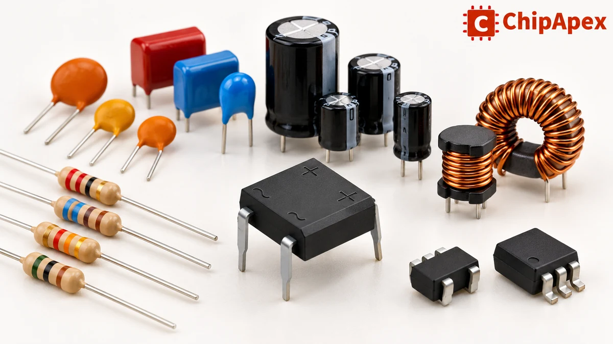
Passive, active and electromechanical are useful starting groups. Catalogs also organize parts by job, including sensing, timing, power conversion and protection. These classifications overlap: a sensor can be a passive resistor or a powered integrated device.
| Family | Main function | Familiar examples | Important selection checks |
|---|---|---|---|
| Resistive components | Set current, divide voltage or measure current | Fixed resistors, potentiometers, current-sense resistors | Resistance, tolerance, power, voltage, temperature coefficient |
| Capacitive components | Store charge, decouple supplies or filter signals | Ceramic, electrolytic and film capacitors | Effective capacitance, voltage, ESR, ripple and temperature |
| Magnetic components | Store magnetic energy, filter or couple signals | Inductors, chokes and transformers | Current, core behavior, losses, frequency and insulation where required |
| Diodes | Rectify, clamp, protect or emit light | Rectifiers, Schottky diodes, TVS devices and LEDs | Voltage, current, leakage, switching behavior and thermal limits |
| Transistors | Switch or amplify | BJTs, MOSFETs and IGBTs | Drive conditions, voltage, current, losses and safe operating area |
| Integrated circuits | Process, regulate, compute or communicate | Amplifiers, converters, controllers, memory and logic | Supply, function, interfaces, timing, package and thermal behavior |
| Timing devices | Establish frequency references or clocks | Crystal resonators and oscillator devices | Frequency, stability, interface, load and startup requirements |
| Sensors | Convert physical conditions into electrical information | Temperature, pressure, position and optical sensors | Range, accuracy, response, interface and installation |
| Electromechanical parts | Connect or physically switch circuits | Connectors, relays and switches | Contact ratings, mating geometry, actuation, environment and life |
| Protection parts | Limit selected electrical faults | Fuses, TVS diodes, MOVs and resettable protectors | Fault conditions, interruption or clamping capability and coordination |
Passive components do not provide power gain. They can dissipate energy, store it temporarily or transfer it between parts of a circuit. Resistors, capacitors and inductors are common examples.
Transistors and powered ICs can control signals and, with energy from a supply, provide amplification or other active functions. Semiconductor devices are often grouped together as active components in catalogs, although classification conventions differ for devices such as diodes. The operating function and datasheet are more useful than treating a catalog label as a design specification.
A passive component still needs an applied signal or stored energy to do anything useful. The description does not mean that it operates independently of a circuit or has no losses.
A resistor’s resistance determines its relationship between voltage and current under the conditions where its resistance model applies. Its power rating, voltage limit and temperature behavior decide whether it can maintain that function in the application.
For an illustrative DC calculation, 10 mA through a 1 kΩ resistor produces a 10 V drop and 0.1 W dissipation. That arithmetic alone does not approve a 0.1 W part: check ambient temperature, mounting, derating and any startup or pulse loading. Precision measurements may also depend on tolerance, temperature coefficient and self-heating.
For capacitors, the marked capacitance is only one part of the specification. Dielectric, voltage, equivalent series resistance, ripple current and temperature can change suitability. A bulk storage capacitor and a high-frequency decoupling capacitor may have different requirements even when their nominal capacitances look similar.
High-dielectric-constant ceramic capacitors can lose effective capacitance under DC bias. Evaluate the actual part’s curves at the intended operating voltage and temperature. The manufacturer explanation of DC-bias behavior describes why nominal and effective capacitance can differ; there is no single reduction percentage that applies to every MLCC.
Inductors require separate checks for saturation and heating. Saturation current concerns the specified loss of inductance under bias; a thermal current rating concerns temperature rise under stated conditions. Compare both with the converter’s current waveform, including peaks. DCR, core losses and frequency behavior can matter as much as inductance.
Rectifier diodes steer current in a power circuit, while signal diodes, Zener diodes and TVS devices are intended for different jobs. Choose a diode in electronics by its actual function before comparing voltage and current numbers.
A diode’s forward voltage changes with current and temperature. Reverse leakage, recovery behavior and capacitance can affect efficiency or signal performance. A bridge rectifier combines a rectifying arrangement into a package, but still needs suitable current, surge and thermal margins.
A transistor can be a small-signal amplifier or a power switch. A BJT’s required drive differs from a MOSFET’s gate-drive requirement. For a MOSFET, threshold voltage indicates the onset of conduction under a stated test condition; it does not prove low resistance at the available gate voltage.
Check on-resistance at the intended drive, switching losses, gate charge and the thermal path. For linear operation or difficult transients, review the safe operating area. A headline current rating does not establish that a device can carry that current on any PCB.
LEDs also require an appropriate current-control method. Their forward voltage is not a regulated supply requirement, and a larger voltage source cannot be connected directly without a suitable limiting or driver arrangement.
ICs group circuit functions into a device. Analog ICs condition continuous signals; digital logic processes defined states. Mixed-signal devices connect those domains through functions such as analog-to-digital conversion. Microcontrollers combine processing with peripherals, but the available interfaces and software ecosystem still need checking.
Compare supply range, input and output limits, timing, power consumption and package. A shared function name, such as operational amplifier or voltage regulator, does not establish pin compatibility or equivalent performance. Requirements such as stability, output loading and startup sequencing can determine whether an otherwise similar part works.
A crystal resonator needs a suitable oscillator circuit. An oscillator device provides a clock function with its own supply and output requirements. When comparing crystals and oscillators, confirm which function the receiving circuit expects. Frequency alone does not specify load capacitance, output format, startup behavior or stability across conditions.
For temperature sensors, distinguish thermistors, RTDs, thermocouples and semiconductor sensors. They differ in excitation, signal conditioning, wiring and measurement behavior. Sensor accuracy is one contributor to system accuracy; installation, reference accuracy and self-heating may also affect the result.
Connectors must fit the mating part and carry the required power or signal. Verify pitch, keying, contact count, current conditions and termination method. Two connectors with the same pitch can still be incompatible. Mechanical retention and repeated mating requirements belong in the specification as well.
Switches connect user or machine actions to a circuit. Momentary tactile switches commonly provide low-current control inputs, while other switch families may offer maintained positions or different load ratings. Confirm the contact arrangement and the exact variant. A switch can feel correct while its height or electrical rating is unsuitable.
Relays use a control input to switch a separate circuit. Coil drive, contact load, inrush, switching rate and isolation requirements need independent review. A resistive-load rating cannot automatically be carried across to a motor or another inductive load.
Protection devices should be selected against a defined fault. A fuse interrupts specified overcurrent conditions; a TVS diode or MOV limits selected overvoltage transients within its ratings. These functions may need coordination. A protection part cannot be approved from its nominal voltage alone, and adding one component does not establish complete product protection.
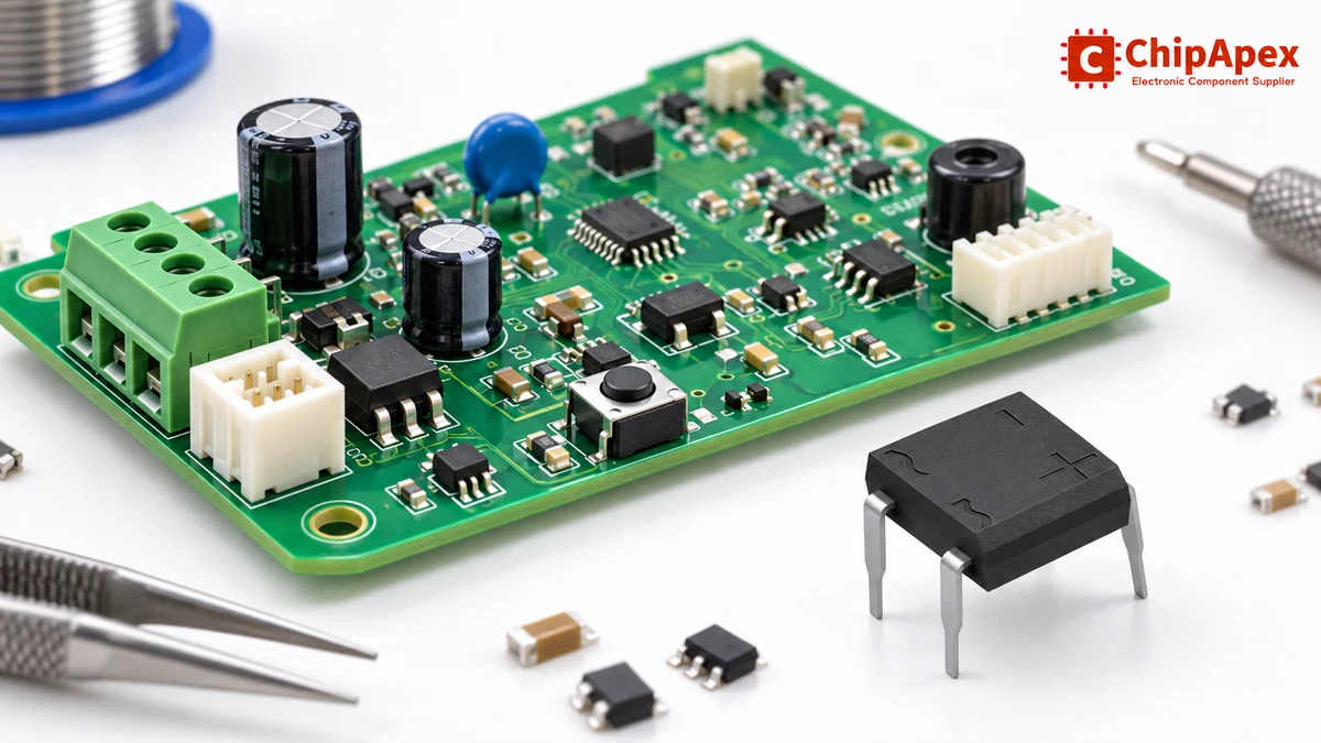
A controller board brings several families into one system. A power input can feed a protection stage and regulator. Capacitors provide local energy storage and decoupling. A sensor path supplies information to the controller, and connectors bring power and signals across the board boundary.
That description is a functional example rather than a complete circuit. The actual design determines whether it needs an external clock, a discrete transistor driver, an amplifier or an isolated interface. Start with the required functions and interfaces before building the parts list.
Physical placement matters. A decoupling capacitor connected through a long, inductive path may not perform as intended at high frequencies. Follow the IC’s application circuit and layout guidance, including the return path. The decoupling tutorial explains how supply noise and connection inductance affect the job of these capacitors.
Prototype checks should include startup, normal load, fast load changes and relevant environmental conditions. A board that functions once at room temperature has not demonstrated every requirement in its specification.
Surface-mount devices attach to pads on a PCB surface. Through-hole devices use leads or terminals inserted through board holes. Both can appear in the same assembly. Select the package around electrical, mechanical and manufacturing requirements.
| Check | Surface-mount device | Through-hole device |
|---|---|---|
| Board interface | Surface land pattern | Hole pattern and lead fit |
| Assembly planning | Placement, solder paste and applicable reflow process | Insertion and applicable soldering process |
| Inspection | Depends on lead visibility and package construction | Lead, joint and insertion checks |
| Mechanical loading | Requires suitable pads and support for the application | Board and lead support still need verification |
| Repair | Tool access and pad condition matter | Hole condition and lead removal matter |
SMD describes the device mounting style; SMT describes the assembly technology. Neither term guarantees a smaller complete system or a higher current capability for every part.
Package abbreviations are also incomplete purchasing descriptions. Confirm dimensions, lead pitch, pin numbering, exposed pads and the recommended PCB footprint. Passive size codes can use different naming systems, so record physical dimensions as well as a code. Polarity and pin-one orientation must match the drawing and assembly data.
Begin with the full manufacturer part number and revision of the document. Check the ordering table to see which suffix controls package, temperature grade, packaging format or another option. A shortened search term can hide a meaningful difference.
Read the recommended operating conditions before applying electrical-characteristic tables. Absolute maximum ratings describe stress limits and do not guarantee normal function at those boundaries. The guide to interpreting logic datasheets explains this distinction and the role of stated test conditions.
For each important parameter, ask whether the number is a minimum, typical value or maximum, and under which supply, load and temperature it applies. A typical curve illustrates behavior; it is not automatically a production guarantee. Check errata, revision notes and application guidance where relevant.
Thermal specifications need the same care. Junction temperature, ambient temperature and a thermal-resistance value are not interchangeable. Board copper, airflow and mounting affect the result. Validate the thermal assumptions for the actual assembly.
Use the schematic, bill of materials and board reference designator first. Common designator conventions can suggest a component family, but project conventions vary. A top marking may be abbreviated or shared by several devices, so combine it with the package, dimensions and circuit connections.
Color bands and numerical codes can identify some resistor values, while many small capacitors have no readable value marking. Semiconductor package shape alone cannot identify its function or pinout. Verify against manufacturer information before ordering a replacement.
For basic checks, remove power and safely discharge stored energy before using resistance or continuity measurements. In-circuit measurements can be influenced by parallel paths. A diode-mode result or resistance reading is a diagnostic clue, not a complete functional qualification of a complex device.
A visual inspection can find damage, corrosion, orientation errors or poor joints. It cannot by itself establish authenticity or remaining life. Escalate uncertain parts to an appropriate identification and inspection process rather than guessing from appearance.
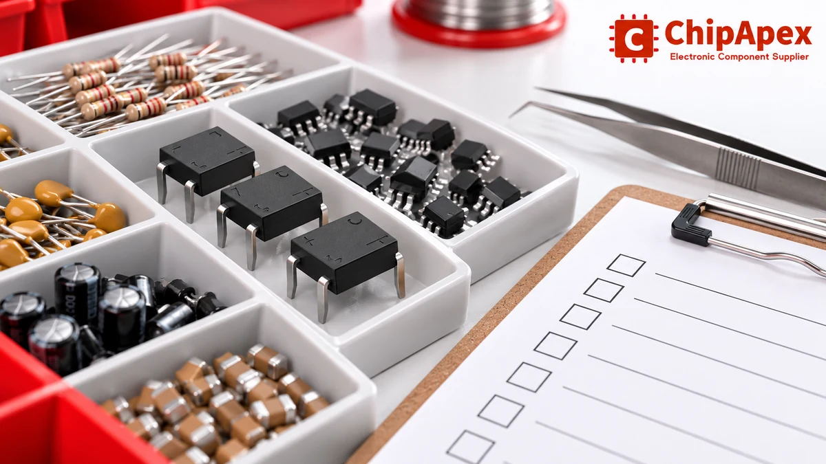
A useful BOM identifies what may be purchased and what changes require approval. Record the manufacturer and exact part number, reference designators, quantity per assembly, required build quantity and acceptable packaging. Include an approved-alternatives field when alternatives are permitted.
| BOM or RFQ field | Why it matters |
|---|---|
| Manufacturer and full part number | Defines the requested orderable variant |
| Quantity and delivery schedule | Separates prototype needs from scheduled production |
| Package and assembly format | Clarifies tape, reel, tray or other handling requirements |
| Approved alternatives | Prevents an unreviewed functional substitution |
| Technical constraints | Preserves critical ratings and mechanical requirements |
| Documentation and inspection needs | Defines the evidence expected with the order |
| Lifecycle and change requirements | Identifies continuity and approval concerns |
A stock listing is a starting point for an availability check. Confirm quantity, lead time, quotation validity and conditions for the exact variant. Evaluate total procurement cost, including assembly format, inspection, minimum quantities and the consequences of a substitute.
Supplier authorization, traceability and inspection evidence answer different questions. Verify any claimed manufacturer authorization through an appropriate current source. Specify required lot, date-code and documentation information where it affects acceptance. A familiar logo or a functioning sample alone does not establish the history of a production lot.
For substitutions, check form, fit and function, then review secondary behavior such as startup, leakage, thermal performance or firmware dependencies. A higher headline rating does not automatically make an alternative suitable. Document approval before it enters production.
Keep electrostatic-sensitive devices within an appropriate ESD-control process during receipt, storage and handling. Protection depends on the handling environment and packaging as well as the person touching the part. The ESD-control principles explain why grounding, material control and defined handling practices work together.
Moisture-sensitive packaging needs separate attention. Follow the device and package instructions for storage, floor life and any permitted recovery process. Do not apply an improvised baking procedure to every component family.
Maintain part identity when reels, trays or bags are split. Retain the information required by the organization’s traceability process and protect parts from contamination or mechanical damage. Incoming acceptance should compare the delivered items with the purchase requirements before assembly begins.
Resistors, capacitors, inductors, diodes, transistors, integrated circuits, connectors and switches appear across many circuits. Sensors, clock devices and protection parts are also common. A particular board uses the families required by its function; there is no mandatory list that every design must contain.
The terms overlap. Electrical components often refer broadly to parts that carry, switch or convert electrical energy. Electronic components commonly include devices used to control and process signals. For purchasing, use the specific function, ratings and manufacturer part number rather than relying on that terminology to establish suitability.
It is a component containing an integrated circuit structure. It may provide a large function, but it usually still needs power, connections and supporting parts. A voltage regulator can need specified capacitors; a processor needs an appropriate power and software environment. Check the application requirements for the exact device.
Only after checking the relevant characteristics. A higher voltage rating does not prove the same capacitance behavior, leakage, package or switching performance. Match the function and mechanical interface, evaluate the full operating conditions, and qualify the alternative in the assembly before approving it for production.
Nominal value is only one attribute. Tolerance, package, material, temperature performance, qualification, packaging and purchasing quantity can affect the offer. Compare exact specifications and commercial conditions. A price difference does not by itself establish better quality or equivalent performance.
Sometimes, but abbreviated markings can be ambiguous. Use the package dimensions, pin count, circuit position and available BOM or schematic information to narrow the identification. Confirm it against manufacturer documentation. An uncertain match should remain unapproved until the electrical and mechanical details are resolved.
Provide the manufacturer, full part number, quantity and required delivery timing. Add the assembly packaging format, approved alternatives and any documentation or inspection requirements. If the part number is unknown, provide the schematic function, dimensions and critical specifications; a generic description is rarely enough to approve a substitute.
Send ChipApex your BOM or exact manufacturer part numbers with quantities and required dates. Flag items that need a specific package, temperature range or approved alternative, and state the documentation needed for acceptance. Confirm the offered variant and supporting information before releasing a production order.
Stop guessing which Op-Amp to use. We break down GBWP, Slew Rate, and Offset Voltage with real engineering insights. Find the right parts like NE5532DR & LM358DR at ChipApex.
View details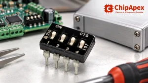
Choose a DIP switch by contact type, coded positions, footprint and signal ratings. Check logic polarity, assembly conditions and PCB configuration behavior.
View details
Discover what DRAM is, how it works, its types, and why choosing authentic, RoHS-compliant DRAM chips matters. Source reliable DRAM from ChipApex—global supplier with full traceability.
View details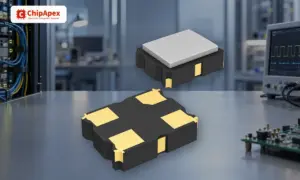
Understand how oscillators generate timing signals, how they differ from crystals, and which frequency, output and stability specs matter when choosing one.
View details
The activity of extra discounts on wholesale prices is in full swing…
Please fill in your contact information and we will send you the latest wholesale price list.

