 ChipApex | Global Electronic Components Supplier

SEARCH
Search Product
Search Post
— IC芯片 | 连接器 | 传感器 | 被动器件 —
Search productSearch post
— IC芯片 | 连接器 | 传感器 | 被动器件 —
The trend of science and technology is changing rapidly.
A bridge rectifier uses four rectifying paths to make both halves of an AC input produce the same output polarity. Select it by reverse-voltage stress, load and charging currents, startup surge, forward loss and the actual thermal installation. A reservoir capacitor changes the current waveform, so DC load current alone is an incomplete sizing method.
A bridge can be one molded four-terminal component or four discrete diodes. Both arrangements need the same electrical checks. This guide focuses on single-phase bridge selection and the capacitor-input supplies often connected to it. A regulated AC-to-DC power supply includes further stages and has its own performance requirements.
During one AC half-cycle, one pair of diodes carries current through the load. During the opposite half-cycle, the other pair carries current while maintaining the output polarity. Two diode junctions are therefore in the conducting path of a conventional bridge.
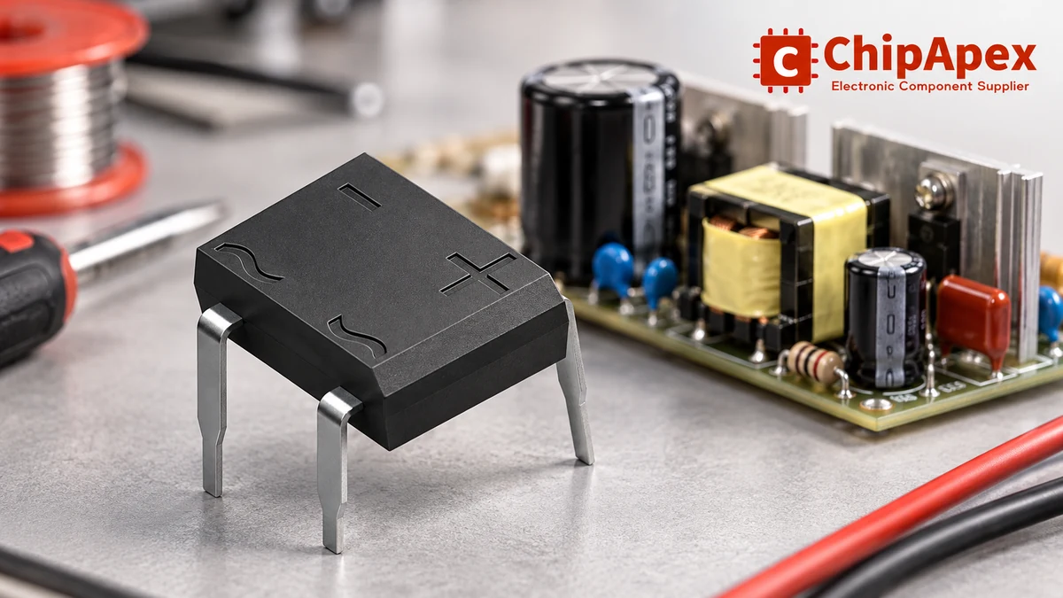
The AC terminals and the positive and negative output terminals must follow the exact package diagram. Do not infer lead order from a similar-looking bridge. Different package families use different physical arrangements, and a reversed connection can damage the supply or load.
When comparing bridge rectifier components, separate a self-contained bridge’s output-current rating from the forward-current rating of an individual diode. For a resistive load, a full-wave output has a ripple frequency twice the AC input frequency. That frequency remains a useful starting point when a reservoir capacitor is added, although the diode current then becomes much more concentrated.
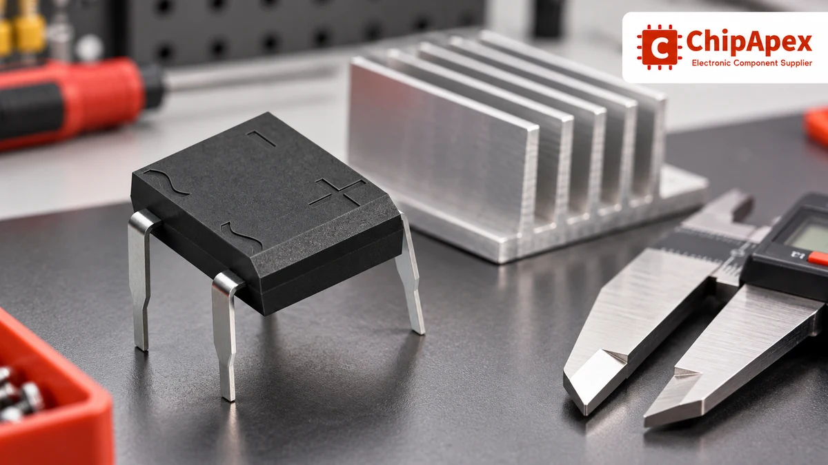
A packaged bridge simplifies placement and ordering. Its terminal layout, body and thermal path are defined together. Discrete diodes can give more freedom over layout, diode technology and heat distribution, but require approval of the complete arrangement.
| Decision | Packaged bridge | Four discrete diodes |
|---|---|---|
| Assembly | One bridge part with a defined terminal layout | Four parts and their orientation must be controlled |
| Thermal review | Package-specific case, ambient or heatsink conditions | Loss and heat paths reviewed for each diode and the PCB |
| Replacement | Match bridge ratings and package drawing | Match every diode and preserve the approved circuit layout |
| Switching behavior | Limited to the chosen bridge family | Diode technology can be selected individually |
General-purpose silicon bridges commonly serve line-frequency rectification. A high-frequency application needs a review of recovery behavior, capacitance and switching loss. A mechanically convenient bridge should not be moved into a switching-frequency circuit without those checks. The broader rectifiers category contains devices with different technologies and intended operating conditions.
For a sinusoidal source, peak voltage is approximately RMS voltage multiplied by the square root of two. Use the highest credible source voltage, then account for relevant transients and the circuit topology when setting the required repetitive peak reverse-voltage rating, VRRM.
For a transformer-fed supply, nominal secondary voltage is only one operating point. Line tolerance and transformer regulation can raise the secondary voltage, particularly at light load. A capacitor-input DC bus can therefore rise above a calculation based only on a fully loaded nameplate voltage.
The source specification for an electrical power transformer should include frequency, secondary-voltage conditions and current capability. Include source impedance in the rectifier review because it influences charging current and startup stress. Transformer VA, rectifier current and DC output current describe different parts of the same supply.
The rectifier design guide distinguishes resistive, capacitor-input and choke-input loads. Use such guidance with its stated assumptions. A single conversion factor should not be treated as a universal transformer-to-DC-current rule.
With a reservoir capacitor, the load can draw current while the bridge is not conducting. The bridge replenishes the capacitor when the AC input rises sufficiently above the capacitor voltage. Charging occurs over portions of the cycle and can produce peak and RMS currents much higher than the DC load current suggests.
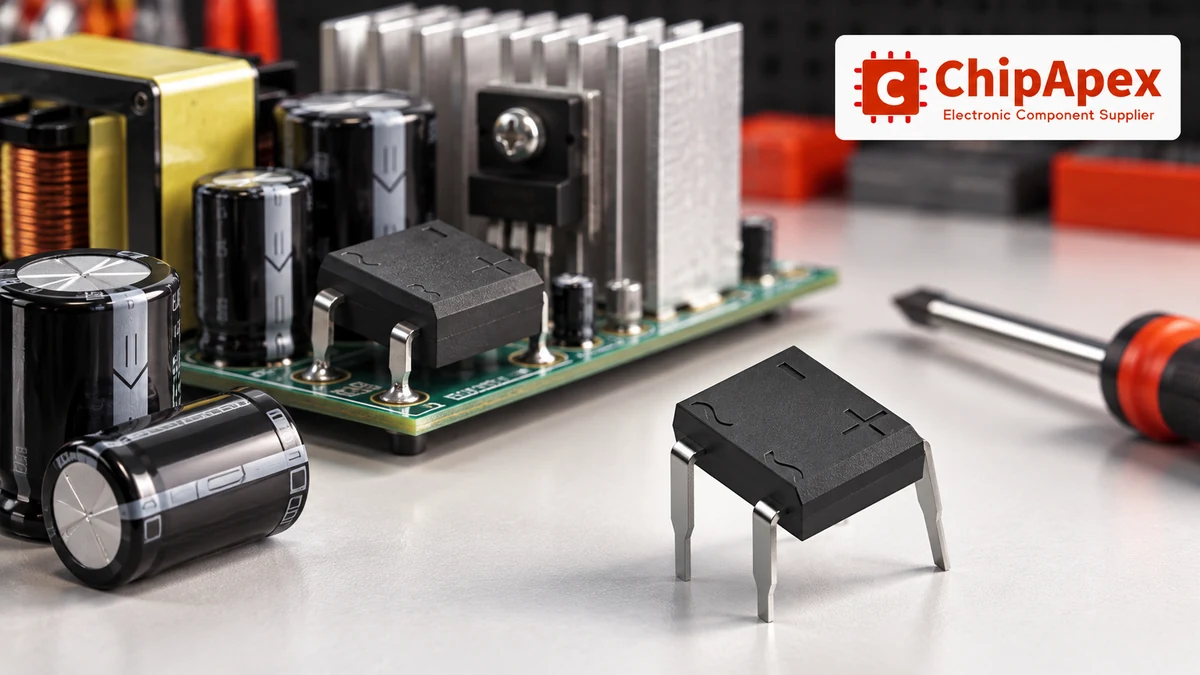
Review average bridge output current, current waveform, repetitive peak behavior and the manufacturer’s rating conditions. The waveform depends on capacitance, load, frequency and source impedance. It also changes across low-line, high-line and startup conditions.
The capacitor needs its own checks. For aluminum electrolytic capacitors, evaluate voltage, ripple-current capability, ESR, temperature and expected service conditions. Increasing capacitance can reduce discharge ripple while increasing startup energy and altering charging pulses. A larger capacitor is not an automatic improvement to the complete supply.
For a single-phase full-wave bridge feeding a reservoir capacitor, a useful first approximation is:
Vpeak ≈ √2 × VAC,RMS − 2VF
ΔVpp ≈ Iload / (2 × fline × C)
The ripple expression assumes approximately constant load current, a relatively small ripple and capacitor discharge over most of the interval between charging peaks. It excludes ESR-related voltage changes, detailed conduction angle and transformer voltage variation. It is a starting estimate for design review, not a guaranteed output specification.
Consider an illustrative 12 V RMS, 50 Hz secondary, a 0.2 A approximately constant load and 2,200 µF of capacitance. Assume 0.9 V forward drop per conducting diode only for this calculation. The estimated charging peak is about 15.2 V, and the simple discharge estimate gives about 0.91 V peak-to-peak ripple.
Those numbers do not establish a regulated 15 V output. Actual forward drop varies with current and temperature. Source sag, capacitor tolerance and pulse-related effects change the result. At light load and high line, the bus can move upward; at low line and heavier load, the valley can fall below a downstream regulator’s required input.
When comparing that unregulated bus with an industrial ac to dc converter, identify which requirements need active regulation, isolation, protection or a specified input range. Rectification alone does not provide all of them.
At startup, a discharged reservoir capacitor can draw a large charging current. Its peak and duration depend on where the AC waveform starts, capacitor voltage, source impedance and any intentional limiting arrangement. A rapid restart can have different conditions from a cold start.
IFSM usually describes a specified non-repetitive surge test. Read its waveform, duration, temperature and repetition conditions. It cannot be substituted for a continuous current rating, and repeated charging events may need separate evaluation.
Coordinate the bridge, inrush limiter and upstream electrical fuses using the actual fault and startup conditions. A fuse’s nameplate current alone does not prove that it protects a bridge. Time-current behavior, available fault current and relevant energy limits need to be considered together.
Two forward drops produce conduction loss in a conventional bridge. A rough constant-drop estimate is P ≈ 2 × VF × IDC, but pulse current and the diode’s changing forward characteristic limit that simplification. Use a waveform-based loss assessment and the manufacturer’s thermal information when the thermal margin is small.
Read whether the current rating assumes a specified case temperature, an aluminum plate, a heatsink or ambient air. A published bridge data sheet, for example, gives substantially different allowable output currents for its stated heatsink-mounted and PCB-mounted conditions. The larger headline current is not an unconditional free-air capability.
Follow the correct thermal path for the package. A case-to-heatsink estimate needs the interface and heatsink path as well as the bridge’s junction-to-case behavior. An ambient thermal-resistance figure may be tied to a particular board and mounting arrangement. Avoid mixing those models or assigning an identical temperature rise to every bridge with the same ampere rating.
A hot bridge can result from inadequate cooling, a demanding charging waveform, excessive load or a poor electrical connection. Excessive ripple can come from a load increase, unsuitable capacitance, capacitor degradation or a missing conduction path. Repeated startup failure can point to charging stress or inadequate coordination.
Inspect and test with power isolated and stored energy safely discharged. In-circuit diode measurements can be affected by parallel paths. A static meter test cannot establish that the bridge meets its voltage, surge or thermal ratings under operation.
RMS describes an AC waveform’s effective value. A reservoir capacitor charges toward the waveform’s peak, reduced by the conducting diodes and affected by source impedance. The capacitor then discharges into the load between charging intervals. Its output varies with loading and input conditions, so a nominal AC RMS value does not translate directly into a regulated DC voltage.
The printed or catalog current may assume a specified case temperature or heatsink installation. Real loss also depends on the conducting waveform and forward characteristic. Check the rating notes, cooling path, enclosure temperature and connections. The current permitted on a PCB in ambient air can be much lower than a rating based on controlled case temperature.
They can implement the same rectification function, but the substitution needs an engineering review. Match reverse voltage, current, surge and switching behavior, and evaluate the PCB layout and thermal paths. Preserve correct polarity and clearances. A collection of diodes with a similar nominal current is not automatically equivalent to the approved bridge assembly.
It can reduce discharge ripple under comparable load conditions, but it also changes charging pulses and startup energy. Review bridge stress, capacitor ripple current, transformer loading and protection coordination. The downstream circuit’s minimum and maximum input voltages still matter. Select capacitance with the source, bridge and load, rather than evaluating ripple alone.
No. A non-repetitive surge rating refers to a defined test waveform and conditions. Average output current, repetitive peaks and RMS heating address different stresses. Check the exact definitions in the part datasheet. If startup occurs repeatedly or before an inrush limiter has cooled, review those operating events explicitly instead of relying on a one-time surge figure.
Only after reviewing the diode technology and switching conditions. Reverse recovery, capacitance and switching loss can become important at higher frequencies. The package’s voltage and current markings do not establish suitable switching performance. Use a bridge or diode arrangement whose datasheet supports the intended waveform, frequency, temperature and circuit application.
For a ChipApex sourcing enquiry, provide the complete part number or bridge drawing, AC source range and frequency, DC load, capacitance, startup conditions, package and cooling arrangement. Include quantity and any required approval or traceability documentation. An alternate should be assessed against those conditions, rather than only by voltage and headline current.
Learn what an RF IC is, how LNAs, PAs, mixers, attenuators and transceivers differ, and how to choose the right RF component. Includes verified part numbers and layout tips.
View details
Learn how DSPs (Digital Signal Processors) enable real-time audio, industrial motor control, 5G communications & medical imaging. Compare DSP vs MCU, choose fixed vs floating-point DSPs, and source authentic DSP chips at ChipApex.
View details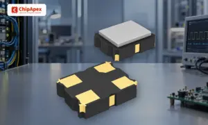
Understand how oscillators generate timing signals, how they differ from crystals, and which frequency, output and stability specs matter when choosing one.
View details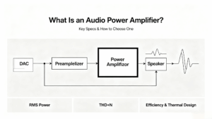
Learn what an audio power amplifier is, the differences between Class D and AB, and how to choose the right IC. Includes PCB layout tips and part recommendations. Shop at ChipApex.
View details
The activity of extra discounts on wholesale prices is in full swing…
Please fill in your contact information and we will send you the latest wholesale price list.

