 ChipApex | Global Electronic Components Supplier

SEARCH
Search Product
Search Post
— IC芯片 | 连接器 | 传感器 | 被动器件 —
Search productSearch post
— IC芯片 | 连接器 | 传感器 | 被动器件 —
The trend of science and technology is changing rapidly.
Optical sensing uses light to detect an object or measure a physical property. A receiver converts incoming light into an electrical signal, which electronics interpret as presence, position, intensity or an image. The right design depends on the light path, target surface, detector and signal processing, as well as the conditions around the sensor.
An optical sensing system follows a light path from a source to a receiver. The source may be an LED or laser, or light already present in the environment. An object changes the received light by blocking, reflecting, absorbing or transmitting it. The receiver and processing circuitry turn that change into useful information.
The detector alone rarely defines the measurement. Lenses set the viewing area; optical filters reject unwanted wavelengths; amplifiers and converters condition the electrical signal. A threshold detector answers whether an object is present. An image sensor preserves spatial information for inspection. Distance measurement needs a suitable method, such as triangulation or time of flight.
ChipApex’s Optical Sensors category provides a starting point for component sourcing. Decide whether you need a bare receiver, an imaging device or a complete industrial sensor before comparing part numbers.
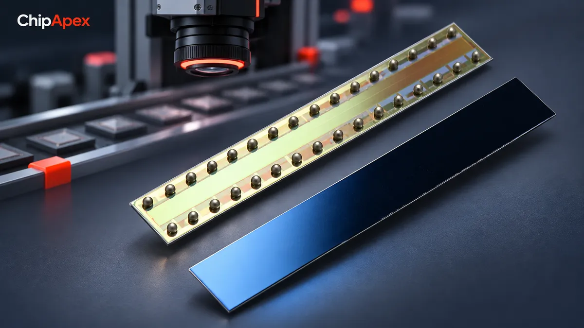
Start with the target and installation geometry. The table compares common object-detection arrangements; it does not describe every form of optical measurement.
| Method | How it detects | Useful when | Main checks |
|---|---|---|---|
| Through-beam | Target interrupts light between separate emitter and receiver | Reliable object counting with access to both sides | Alignment, target size and beam diameter |
| Retroreflective | Target interrupts light returned by a reflector | Wiring is practical on one side only | Reflector placement, shiny or transparent targets |
| Diffuse reflective | Receiver detects light returned from the target | Space permits a compact, one-sided arrangement | Color, finish, angle and background |
| Background suppression | Optical geometry distinguishes the target from a more distant surface | A conveyor or machine wall could cause false detection | Cutoff behavior and target variation |
| Imaging | An array captures spatial light information | Shape, position or pattern is needed | Optics, exposure, illumination and data interface |
Transparent objects require particular care. A clear target may attenuate or redirect a beam without blocking it completely. Use a detection arrangement intended for the material and verify its margin with actual samples. [1]
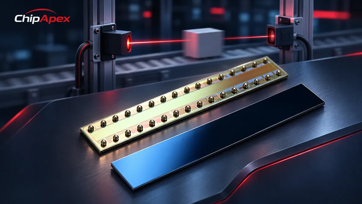
A photodiode produces photocurrent and often needs a carefully designed amplifier. A phototransistor adds internal current gain, which can simplify presence detection, with tradeoffs in linearity and response. An image sensor contains multiple photosensitive elements and a readout arrangement that preserves spatial information.
For simple light-dependent switching, consider the Phototransistors category. For line inspection, the listed EPC901-CSP32-033 is an example of an image-sensor component in the ChipApex catalog. Its listing identifies a linear CCD sensor; it should not be treated as a complete camera or a ready-to-use distance sensor. Confirm the manufacturer’s datasheet, optics and readout requirements for the intended design.
Optical sensing also includes fiber-based measurement and spectroscopy. Those methods use different light interactions and system architectures. A general-purpose object-detection sensor cannot automatically replace them.
Dark material can return less light than a pale reference target. A polished surface can send a strong reflection away from the receiver, or reflect an unwanted source toward it. Tilt, texture and changing distance can produce larger signal changes than the difference between two nominal sensor specifications.
Modulated illumination and optical filtering can reduce interference. They do not guarantee immunity to direct sunlight, another emitter at a similar wavelength or saturation in the receiver. Check the sensor’s stated ambient-light conditions and test the worst likely light direction. Shielding the optical path can be more effective than increasing sensitivity.
Dust, condensation and scratches change the optical path over time. Leave enough detection margin for contamination and allow access for cleaning. Manufacturer guidance on photoelectric sensing explains why geometry and background rejection belong in the initial design. [2]
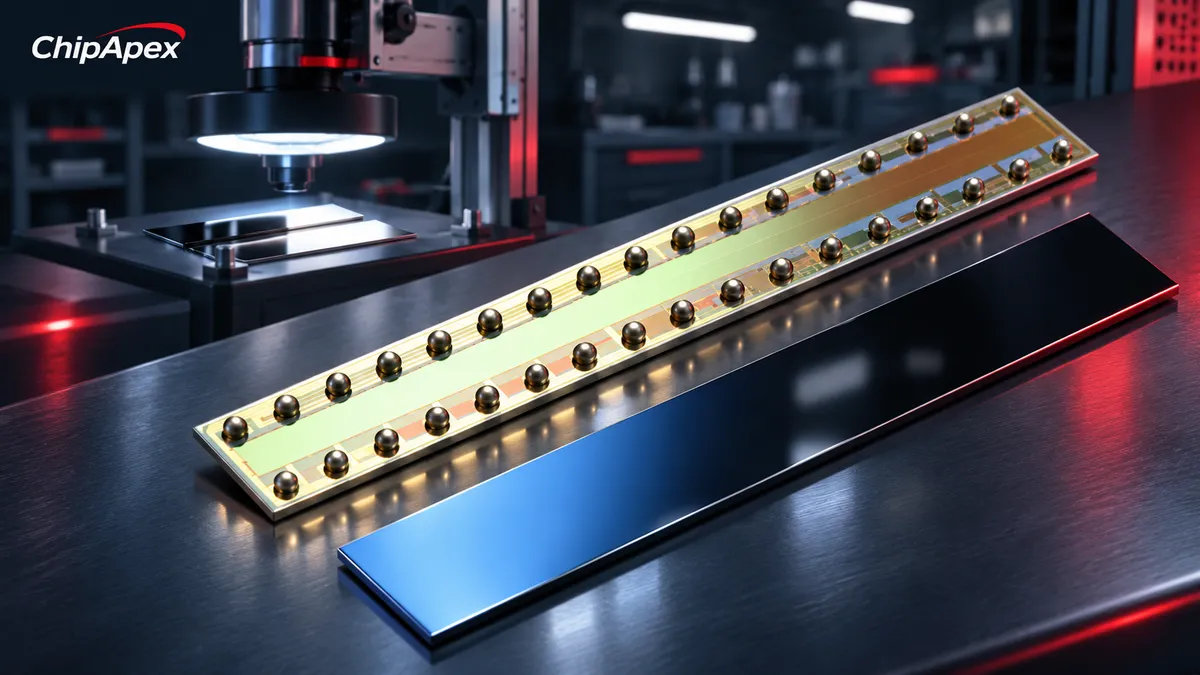
Translate movement into an electrical timing requirement. In an illustrative conveyor calculation, a 2 mm feature moving at 1 m/s passes a fixed sensing point in 2 ms. The detector, filtering and controller input must resolve a shorter event with adequate margin. This is a design calculation, not a measured specification for any catalog product.
Also consider the light spot diameter. A wide spot can average a small feature with its surroundings. Exposure time matters for imaging because a moving target can blur during integration. For threshold sensors, hysteresis can prevent chatter, but it can also affect the point at which the output changes state.
Record the electrical interface: supply voltage, analog or digital output, logic thresholds, output polarity and cable length. A bare phototransistor, an open-collector sensor and an industrial PNP output require different input circuits.
Test representative light and dark samples, shiny and rough finishes, minimum and maximum distance, and the smallest target. Repeat the checks under expected ambient lighting and with realistic alignment tolerance. For a moving process, test at operating speed rather than moving the sample by hand.
Log false detections as well as missed objects. If a system works only at maximum sensitivity, investigate the optical arrangement before freezing the component selection. An emitter-on versus emitter-off comparison can help separate returned illumination from background light when the design supports it.
No. Ambient-light sensors measure existing light, and cameras can use environmental illumination. Active object-detection systems supply their own illumination to create a more controlled signal. The source wavelength and receiver sensitivity must be compatible.
An optical sensor can perform proximity detection, but proximity sensing also includes inductive, capacitive and other methods. Choose by target material, installation space, environment and required detection behavior.
Some can, using arrangements designed for transparent targets. Clear plastic may transmit most of the beam or create confusing reflections. Verify the actual material, thickness, angle and background rather than assuming that all optical sensors will detect it.
No. Receiver bandwidth, exposure, filtering, output electronics and controller sampling determine system response. Use the specified electrical response or acquisition time when calculating the maximum target speed.
Provide the target material, feature size, distance, speed, light conditions and output requirements. For a replacement, include the full part number and package. ChipApex inquiries should identify whether the requirement is for a detector component, an imaging device or an assembled sensor.
Understand how motion sensors work. Compare PIR, radar and ultrasonic sensing, then check presence detection, false triggers, optics and signal conditioning.
View details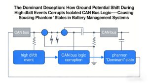
Ground potential shift during high dI/dt regen braking causes isolated CAN receivers to output false dominant states, locking EV BMS networks. Discover robust solutions like TJA1044GT/3Z + common-mode filtering validated by ChipApex.
View details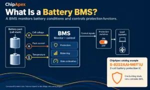
A battery BMS, or battery management system, monitors a battery and controls how it is used within defined operating limits. It measures conditions such as cell voltage, pack current and temperature. Depending on the design, it can also balance ce...
View details
An inductor is approximately linear only over a specified operating range. In the ideal model, its inductance stays constant and voltage equals inductance times the rate of current change. A real magnetic core can approach saturation as current ri...
View details
The activity of extra discounts on wholesale prices is in full swing…
Please fill in your contact information and we will send you the latest wholesale price list.

