 ChipApex | Global Electronic Components Supplier

SEARCH
Search Product
Search Post
— IC芯片 | 连接器 | 传感器 | 被动器件 —
Search productSearch post
— IC芯片 | 连接器 | 传感器 | 被动器件 —
The trend of science and technology is changing rapidly.
A motor controller manages how an electric motor starts, stops and runs. Depending on the system, it regulates direction, speed, torque or position and handles faults. Its implementation can range from switching equipment to an electronic control board with firmware, sensors and a power stage matched to the motor.
The controller decides what the motor should do; the driver provides the switching and current needed to make it happen. A gate driver operates power-transistor gates, while a motor-driver IC may integrate the power switches. Commercial products often combine these functions, so the names alone do not establish what a device includes.
An external microcontroller might calculate a speed loop and send PWM commands to a driver. An integrated BLDC device can include the commutation algorithm. At larger power levels, the control electronics may command a separate inverter. Always read the functional block diagram and interface description.
Browse Motor Drivers, Controllers by motor type and integration level. A package that fits the PCB does not establish compatibility with the motor or its control method.
| Motor | Typical drive arrangement | What to establish first |
|---|---|---|
| Brushed DC | H-bridge for reversing, or simpler switching for one direction | Supply range, running current, startup and stall behavior |
| Bipolar stepper | Two controlled winding-current paths | Phase current, winding parameters and step interface |
| BLDC or PMSM | Electronic commutation with a three-phase power stage | Feedback method, startup torque and control algorithm |
| AC induction | Suitable AC drive, often a variable-frequency drive | Motor ratings, supply and operating speed range |
A brushed motor commutates mechanically. A BLDC motor requires electronic commutation. A stepper drive controls winding current in a sequence, often using microstepping. These differences prevent a generic voltage-and-current match from being sufficient. Manufacturer motor-control resources cover the distinct control approaches. [1]
For a component example, ChipApex lists 0C621-003-XTD in its motor-driver catalog. Treat it as a part-number-specific sourcing route: verify its original datasheet and microstepping interface before considering a replacement or a new design.
Motor current changes with mechanical load and operating state. A brushed DC motor has little back electromotive force at standstill, so startup can demand much more current than steady running. A blocked shaft can sustain a damaging load unless the drive limits current or disconnects it.
For a simplified brushed-motor estimate, stall current is supply voltage divided by winding resistance. An illustrative 12 V motor with 2 Ω winding resistance would draw about 6 A at stall before accounting for driver drops, wiring and temperature effects. This is a calculation, not a tested motor rating. Use the manufacturer’s data or controlled measurement for the real design.
A peak current headline also needs a duration. Check the driver’s continuous thermal capability, current-limit behavior, PCB requirements and protection timing. Current limiting can constrain available starting torque. Thermal shutdown protects against some overload conditions but should not be the normal operating control. [2]
PWM changes switching duty cycle. In a simple brushed-motor drive it influences the applied average voltage, but the resulting speed still depends on load. Closed-loop speed control measures actual speed and adjusts the command. Position control additionally needs a position reference or an appropriate estimation method.
Microstepping sets intermediate winding-current levels in a stepper motor. It can improve motion smoothness, although commanded microsteps do not guarantee equal mechanical position increments under every load. Check acceleration, resonance, torque margin and missed-step detection where position matters.
For BLDC drives, sensored and sensorless approaches have different startup and low-speed behavior. Choose the control method around required torque, acoustic behavior and feedback availability. Firmware tuning can be part of the component integration effort.
Stopping modes change the power flow. Coasting allows the motor to slow with relatively little commanded braking torque. Dynamic braking dissipates energy in a defined electrical path. Regenerative operation can return energy to the supply, which must be able to accept it or have another way to limit the bus voltage.
Do not assume a bench supply can absorb returned energy. Check bus capacitance, transient suppression and the drive’s recommended braking arrangements. The appropriate solution depends on motor energy, inertia and stopping frequency.
Protection checks should include undervoltage, overcurrent, short circuits, thermal limits and fault reporting. External MOSFET stages also need appropriate switching control to prevent simultaneous conduction in a half bridge. Follow the chosen device’s layout and decoupling instructions; high-current loops and sensing connections affect operation. [3]
First identify the exact motor and required motion profile. Record minimum and maximum supply voltage, including transients. Establish running current, startup requirements and credible stall conditions. Then choose feedback, command interface and stopping behavior.
Compare the full current path, including power switches, shunts, connectors and PCB copper. Validate at the highest intended enclosure temperature and under the actual duty cycle. Test startup under load and controlled fault recovery, with a setup that prevents uncontrolled movement.
Finally confirm the complete ordering code, package and supported development tools. Replacing an older driver may require changes to current sensing, firmware or pin assignments even when its nominal supply rating appears similar.
No. The commutation method, number of phases, current regulation and feedback requirements must match. A brushed DC H-bridge does not by itself provide the three-phase sequence required by a BLDC motor.
No. Some accept simple logic, PWM or step-and-direction commands. Others contain configurable control algorithms or run user firmware. Check which functions are fixed, register-configured or software-defined.
Running current is only part of the requirement. Include startup, acceleration, braking and stall behavior, along with permitted duration and current limiting. Verify the thermal conditions behind the stated continuous rating.
It depends on loss and the available heat path. PCB copper, exposed-pad layout, airflow and ambient temperature can limit continuous output. A driver that survives a short bench run may still overheat in an enclosure.
Provide the full motor or existing driver part number, motor type, supply range, phase or stall current, feedback method and command interface. Include package constraints and quantity. Candidate parts still require datasheet and application checks before substitution.
Compare gas sensor technologies, cross-sensitivity and calibration needs. Define the gas, range and environment before choosing a sensing component.
View details
Learn how audio amplifiers work, compare Class AB vs. Class D, and discover key metrics (THD+N, SNR). Source authentic TI/ST audio ICs at ChipApex for your design.
View details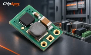
Select a DC-DC converter by input range, topology, isolation and temperature. Compare ripple, efficiency and load limits before choosing a component.
View details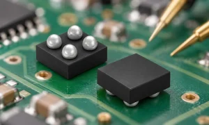
A comparator checks which of two input voltages is higher and changes its output state accordingly. It is useful when an analog signal must trigger a clear decision, such as an overvoltage warning or sensor threshold. Its input range, output type,...
View details
The activity of extra discounts on wholesale prices is in full swing…
Please fill in your contact information and we will send you the latest wholesale price list.

