 ChipApex | Global Electronic Components Supplier

SEARCH
Search Product
Search Post
— IC芯片 | 连接器 | 传感器 | 被动器件 —
Search productSearch post
— IC芯片 | 连接器 | 传感器 | 被动器件 —
The trend of science and technology is changing rapidly.
Thermal management controls the temperature of electronic components by limiting heat generation, providing paths for heat to leave and monitoring critical locations. It combines electrical design, PCB layout, materials, cooling and protection. The objective is to keep each component within its specified operating conditions across the intended load and environment.
Heat follows power loss. In a linear regulator, a useful first approximation is voltage drop multiplied by load current, with quiescent consumption considered separately. In switching circuits, conduction loss and switching loss both matter. Resistive losses also occur in connectors, traces and windings.
Start with the actual operating profile. A short current pulse and a continuous load can have the same peak power yet produce different temperatures. Switching frequency, input voltage and hot-state resistance may change the loss. A single room-temperature efficiency figure rarely defines the worst case.
ChipApex’s Thermal Management category is a component-sourcing entry point. Confirm each device’s function against its manufacturer documentation before choosing it for temperature sensing, fan control or protection.
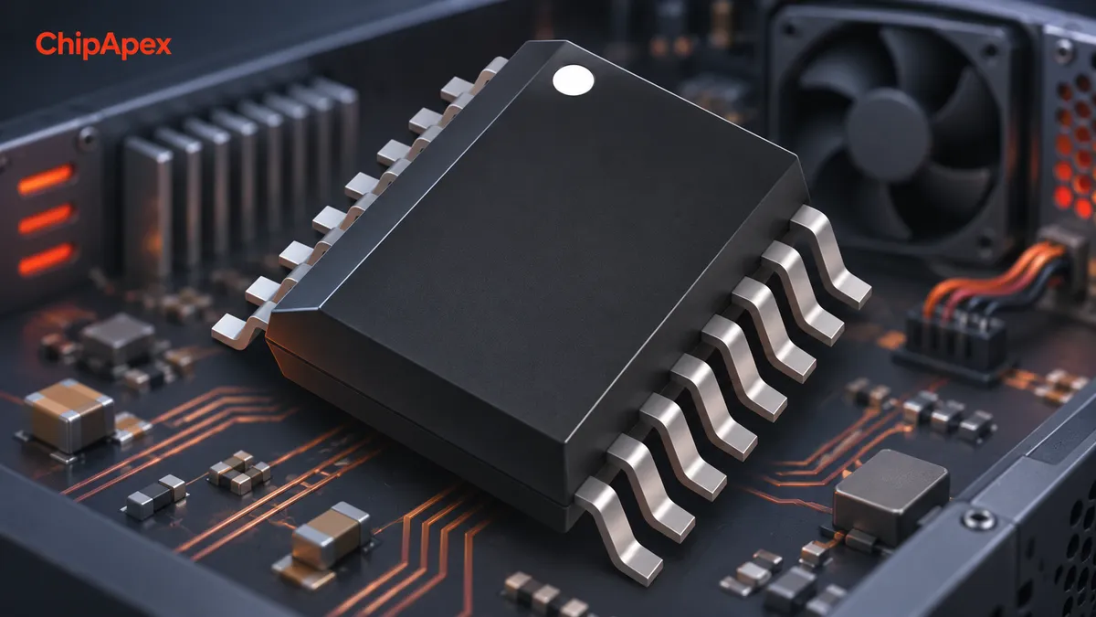
Conduction transfers heat through solids and interfaces. The package, solder, PCB copper and thermal interface material form parts of this path. Convection transfers heat from a surface to moving air or liquid. Radiation exchanges energy between surfaces and becomes relevant according to temperature, area and surface properties.
| Design measure | What it changes | Practical limitation |
|---|---|---|
| Copper planes and thermal vias | Spread heat into the PCB | Layout, stackup and via construction matter |
| Heat sink | Adds area for heat transfer | Needs a suitable interface and available airflow |
| Thermal pad or paste | Reduces interface air gaps | Thickness, pressure and assembly tolerance affect resistance |
| Fan or blower | Increases forced airflow | Obstruction, dust, acoustic limits and fan failure |
| Cold plate or liquid loop | Carries heat into a coolant circuit | Plumbing, reliability and system complexity |
Improving one element may leave another as the bottleneck. A larger heat sink will have limited value if the package-to-sink interface is poor or hot exhaust recirculates into the intake.
Thermal resistance describes temperature rise per unit heat flow under defined conditions, typically in °C/W. Datasheet junction-to-ambient resistance, θJA, depends strongly on the test board and environment. It is not a universal constant for the package in every application. TI’s thermal-metrics note explains the limits of using it for system temperature prediction. [1]
Junction-to-case resistance, θJC, describes a specified path under particular measurement conditions. It should not automatically be multiplied by total dissipation and added to an arbitrary measured case temperature. Real heat flow divides between the board, case and surrounding air.
Thermal characterization parameters such as ΨJT serve a different purpose from thermal resistance. Their application depends on the measurement arrangement. Choose a model suited to the actual heat path, then validate the board rather than treating datasheet symbols as interchangeable.
For an illustrative system with an established effective thermal resistance of 20 °C/W, a 2 W steady-state loss produces an estimated 40 °C rise. At 50 °C local ambient, that implies about 90 °C at the modeled point. The assumed resistance must be justified for that system; this is not a prediction for a named ChipApex product.
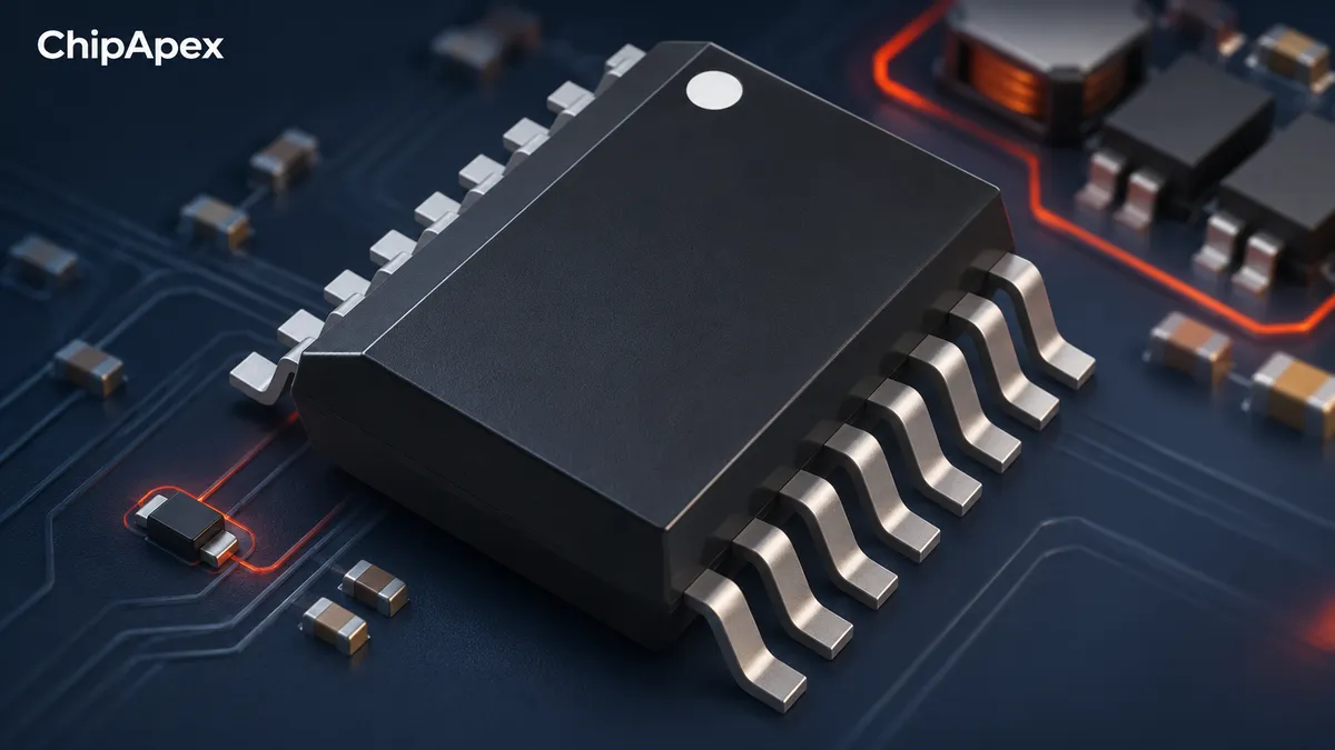
Place the sensor where its reading can represent the condition you need to control. A sensor near a power IC can track board heating; one in an air inlet measures incoming air. Neither automatically measures the semiconductor junction. Contact, copper paths and thermal mass affect offset and response delay.
A remote measurement can be useful when the controlled component is inaccessible, but establish how it relates to the hotspot during startup and rapid load changes. A sensor attached to a large heat sink may react after the device has already heated substantially. Characterize the delay before setting a protection threshold. [2]
For active cooling, the ADT7470ARQZ is a catalog example to investigate. The manufacturer identifies the ADT7470 family as a temperature-sensor hub and fan controller. Verify the supported sensor connections, fan interfaces and complete ordering-code requirements against the datasheet. [3]
Fan control adjusts cooling during ordinary operation. Overtemperature protection responds when an unsafe or unacceptable condition develops. A system can need both, particularly when a fan can stall or a vent can become blocked.
Use hysteresis or an appropriate control curve to avoid rapid fan cycling. Monitor fan operation where failure could matter. Consider the startup state, missing sensor behavior and recovery after a fault. Repeated thermal shutdown indicates that the operating conditions or design need attention.
A ptc temperature sensor can contribute to sensing or protection when its curve and circuit suit the application. A thermal fuse provides a different function: a specified non-resettable thermal cutoff. Neither is interchangeable with a fan controller, and protective devices require their own electrical and mounting checks.
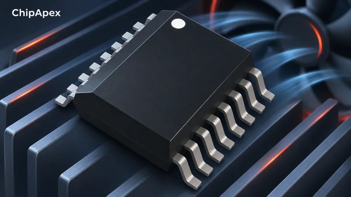
Test a representative assembled board inside its intended enclosure. Include the highest specified ambient, realistic load combinations and installation orientation. Measure local air temperature and relevant component temperatures with instruments suitable for the surfaces involved.
Infrared measurements depend on emissivity and visibility. A shiny metal surface can mislead a thermal camera, while a thermocouple can disturb a small heat path if poorly attached. Document placement and compare results using a consistent method.
Check transient operation as well as the stabilized temperature. Include degraded cooling conditions that belong in the system’s requirements, such as reduced airflow. Retain margin below the component’s limit; maximum ratings are not recommended continuous operating targets. [4]
No. It starts with power loss and extends through the full heat path, enclosure and control strategy. A heat sink is one possible element. Layout changes or lower circuit loss can be more useful when the board is the main heat path.
No. A sensor measures a condition. It can enable throttling, fan control or shutdown, but it does not remove meaningful heat by itself. The system still needs an adequate thermal path for normal operation.
Treat it as a fault response with device-specific limits. It may not protect nearby components or cover every failure mode. The normal operating design should remain within its specified conditions without repeatedly reaching shutdown.
No. Interface performance also depends on thickness, contact area, compression and the adjoining surfaces. A highly conductive but poorly fitted pad can create a worse installed thermal path than a correctly selected alternative.
Provide dissipation, ambient range, available space, cooling method and the temperature to be measured or controlled. For fan-control parts, include fan type, interface, sensor arrangement and fault-response needs. ChipApex can receive the full part number and quantity for sourcing inquiries.
Learn how a TRIAC switches AC loads. Understand triggering, latching, holding current, phase control and thermal limits before choosing a component.
View details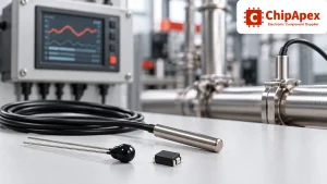
Compare thermistors, RTDs, thermocouples and temperature ICs. Learn how range, accuracy, response, interfaces and mounting affect component selection.
View details
Learn what an integrated circuit is, how ICs work, the main types and the specs to check before choosing a part for your design with ChipApex.
View details
A positive temperature coefficient (PTC) thermistor is a resistor whose resistance rises as its temperature rises. Depending on its material and curve, that change can be gradual or very steep around a transition temperature. Designers use PTC par...
View details
The activity of extra discounts on wholesale prices is in full swing…
Please fill in your contact information and we will send you the latest wholesale price list.

