 ChipApex | Global Electronic Components Supplier

SEARCH
Search Product
Search Post
— IC芯片 | 连接器 | 传感器 | 被动器件 —
Search productSearch post
— IC芯片 | 连接器 | 传感器 | 被动器件 —
The trend of science and technology is changing rapidly.
A TRIAC is a three-terminal semiconductor device that can conduct current in either direction when triggered. It is commonly used to control AC loads because it can switch both halves of an AC waveform. Its terminals are usually called MT1, MT2 and gate, although datasheets may use A1 and A2.
Selecting a triac requires more than matching current and voltage. Gate sensitivity, latching current, holding current, commutation and thermal conditions determine whether it will operate reliably with a particular load.
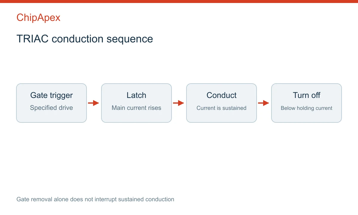
A suitable gate signal triggers conduction between the main terminals. Once the main current is sufficient, the TRIAC can remain on after the gate signal is removed. It normally turns off when the main current falls below the holding current and the device can recover its blocking state.
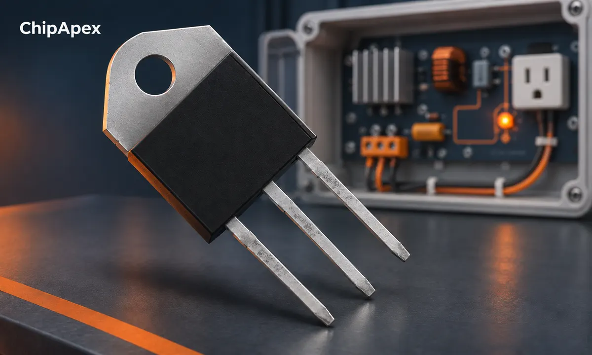
This behavior differs from a MOSFET whose gate continuously controls its state. Removing the TRIAC gate signal does not necessarily stop an existing current. That is why a conventional TRIAC is usually unsuitable for simple DC switching: the current may never naturally fall low enough to turn it off.
AC operation makes natural turn-off possible, but current zero and voltage zero need not occur together. An inductive load can shift the current waveform. The device must regain its blocking ability under the actual voltage and current conditions.
| Parameter | Meaning | Practical consequence |
|---|---|---|
| Gate trigger current | Gate current required under stated conditions | Driver must meet the relevant quadrant and temperature requirements |
| Latching current | Main current needed to remain on after triggering ends | A short gate pulse may fail at light load |
| Holding current | Main current below which conduction cannot be sustained | Low-current loads may turn off unexpectedly |
These parameters are related but not interchangeable. A gate pulse can trigger a device without establishing enough load current for sustained conduction. Conversely, a conducting device may remain on with less current than was needed to latch initially.
The manufacturer's holding-current application note explains why this parameter matters in practical circuits. Check its conditions and the selected device's current datasheet rather than applying one typical value to all TRIACs.
Gate polarity relative to MT1 and the polarity at MT2 define triggering quadrants. Sensitivity can differ across quadrants, and some devices are designed for operation in only particular quadrants. Match the gate driver to the part's supported operation.
Phase-angle control delays triggering within each AC half-cycle. Changing that delay changes the portion of the waveform delivered to the load. The resulting current depends on the load, so the firing angle does not translate to the same power relationship for every appliance.
Zero-cross switching turns on near a voltage zero crossing under the driver's defined conditions. It is often useful for on/off or burst control of suitable loads. A zero-cross optotriac driver is generally inappropriate when arbitrary phase-angle firing is required.
An optotriac driver and a load-switching power TRIAC are different components. The driver may provide an isolated trigger path, but it is not necessarily rated to carry the load. Isolation also depends on the exact device rating and complete PCB implementation.
LED drivers and other electronic loads can behave differently from resistive heaters. Minimum current, input capacitance and control compatibility may lead to flicker or unstable operation. A generic “dimmable” description is not enough to establish compatibility with every TRIAC controller.
Check repetitive blocking voltage against the operating voltage and anticipated transients. Then assess RMS current, surge capability, conduction loss and junction temperature under the actual load waveform. A current rating stated at a controlled case temperature does not mean the package can carry that current without thermal management.
The power path, heatsink interface, enclosure temperature and airflow all affect the result. Tab isolation varies by package. Do not assume that a metal tab is electrically isolated or that two visually similar packages share the same pinout.
For a preliminary thermal estimate, combine device dissipation with the relevant thermal resistances and ambient or case temperature. Use the manufacturer's on-state characteristics and waveform-specific method. A rough calculation is useful for screening, but final validation needs representative operating conditions.
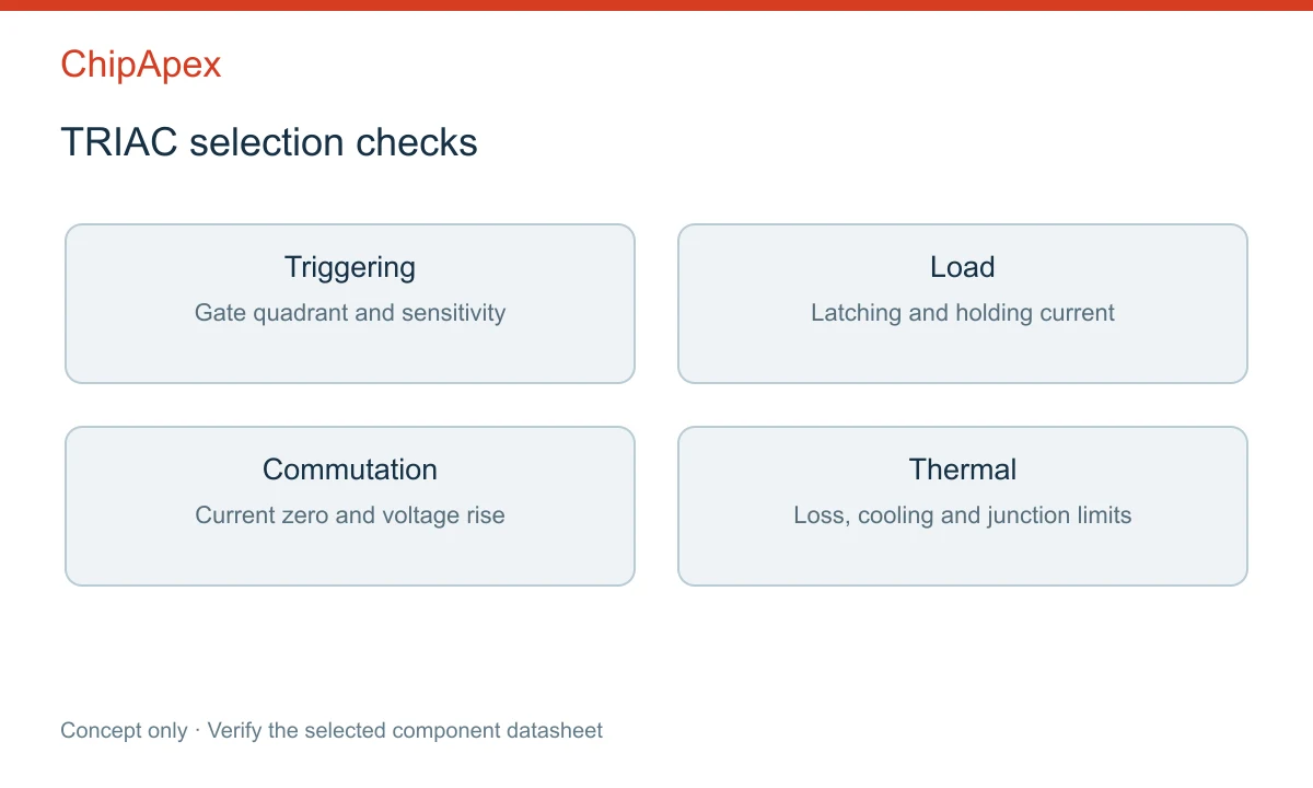
A rapid voltage change can cause unwanted triggering, while difficult current and voltage conditions during turn-off can cause commutation failure. Inductive loads deserve particular attention. Static dV/dt and commutating dV/dt describe different conditions and should not be treated as the same specification.
Snubbers and transient protection may be needed, but their values depend on the circuit. A snubber can also pass leakage current when the TRIAC is off, affecting small electronic loads. Follow the relevant manufacturer application guidance and verify the resulting behavior.
For EMI control, common mode chokes address a different noise mode from components intended for differential-mode filtering. Filter choice should follow measurements and the load-control architecture. Do not add a generic filter and assume compliance.
Browse triacs using the load type, AC voltage and frequency, RMS and surge current, gate driver, package and thermal conditions. Send ChipApex the preferred part number, quantity and replacement constraints. Include any required isolation or application approvals as explicit requirements rather than assumptions.
If the circuit needs mechanical contact separation or very low off-state leakage, compare the requirements with suitable relays. This is an architecture decision: semiconductor switching and mechanical contacts have different tradeoffs.
It may turn on, but removing gate drive usually will not turn it off while current remains above the holding current. Conventional TRIAC circuits are therefore generally intended for AC loads.
No. A conventional SCR conducts in one main-current direction. A TRIAC supports bidirectional conduction, with its own triggering and commutation characteristics.
The load may not provide enough latching or holding current, or its driver may be incompatible with the control method. Leakage and timing can also contribute.
Only after checking gate requirements, voltage, holding current, commutation, package, pinout and thermal behavior. A higher headline current rating is not sufficient.
The power TRIAC itself does not provide control-to-load galvanic isolation like an isolated driver. Any isolation must be established by the specific circuit and rated components.
An inductor is approximately linear only over a specified operating range. In the ideal model, its inductance stays constant and voltage equals inductance times the rate of current change. A real magnetic core can approach saturation as current ri...
View details
An inertial measurement unit (IMU) measures motion using an accelerometer and a gyroscope in one device or module. The accelerometer senses specific force, including the effect of gravity; the gyroscope senses angular rate. Software can combine th...
View details
Learn how DSPs (Digital Signal Processors) enable real-time audio, industrial motor control, 5G communications & medical imaging. Compare DSP vs MCU, choose fixed vs floating-point DSPs, and source authentic DSP chips at ChipApex.
View details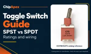
Compare SPST and SPDT toggle switches, understand AC/DC ratings, and follow wiring examples. Check contact action, mounting and parts in the ChipApex catalog.
View details
The activity of extra discounts on wholesale prices is in full swing…
Please fill in your contact information and we will send you the latest wholesale price list.

