 ChipApex | Global Electronic Components Supplier

SEARCH
Search Product
Search Post
— IC芯片 | 连接器 | 传感器 | 被动器件 —
Search productSearch post
— IC芯片 | 连接器 | 传感器 | 被动器件 —
The trend of science and technology is changing rapidly.
The main difference between a rheostat and a potentiometer is how the adjustable resistance is used. A rheostat uses two electrical connections to vary resistance in a current path. A potentiometer uses three connections to form an adjustable voltage divider. Some three-terminal potentiometers can be wired for rheostat operation within their ratings.
The terms do not establish power capability by themselves. A small panel potentiometer should not be assumed suitable for controlling a high-current load just because it can be connected with two terminals.
A typical potentiometer has two ends of a resistive track and a movable wiper. The resistance between the two ends stays approximately constant as the shaft turns. The resistance from the wiper to either end changes with position.
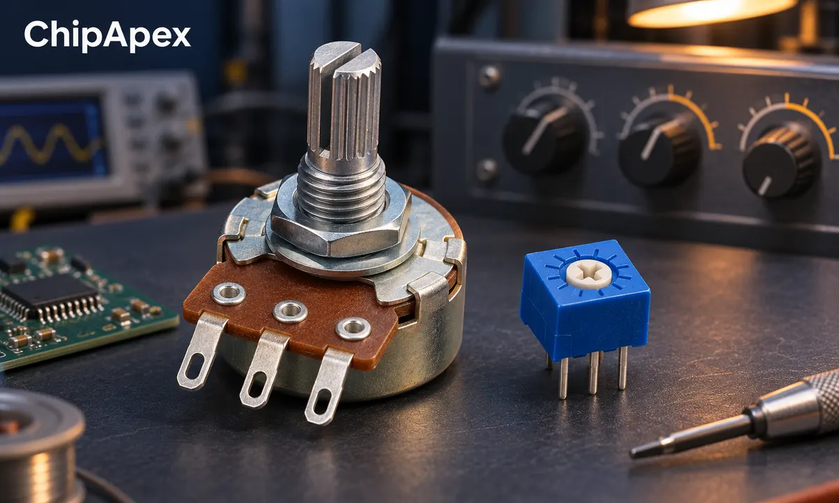
In voltage-divider operation, the two track ends connect across a suitable voltage and the wiper provides an adjustable fraction of it. In rheostat operation, the circuit uses the wiper and one track end as a variable resistance.
| Feature | Potentiometer operation | Rheostat operation |
|---|---|---|
| Electrical connections | Three | Two |
| Main function | Adjust voltage ratio | Adjust series resistance |
| Common use | Setpoint or signal level | Current or resistance adjustment |
| Main limitation | Loading and wiper behavior | Current and active-track dissipation |
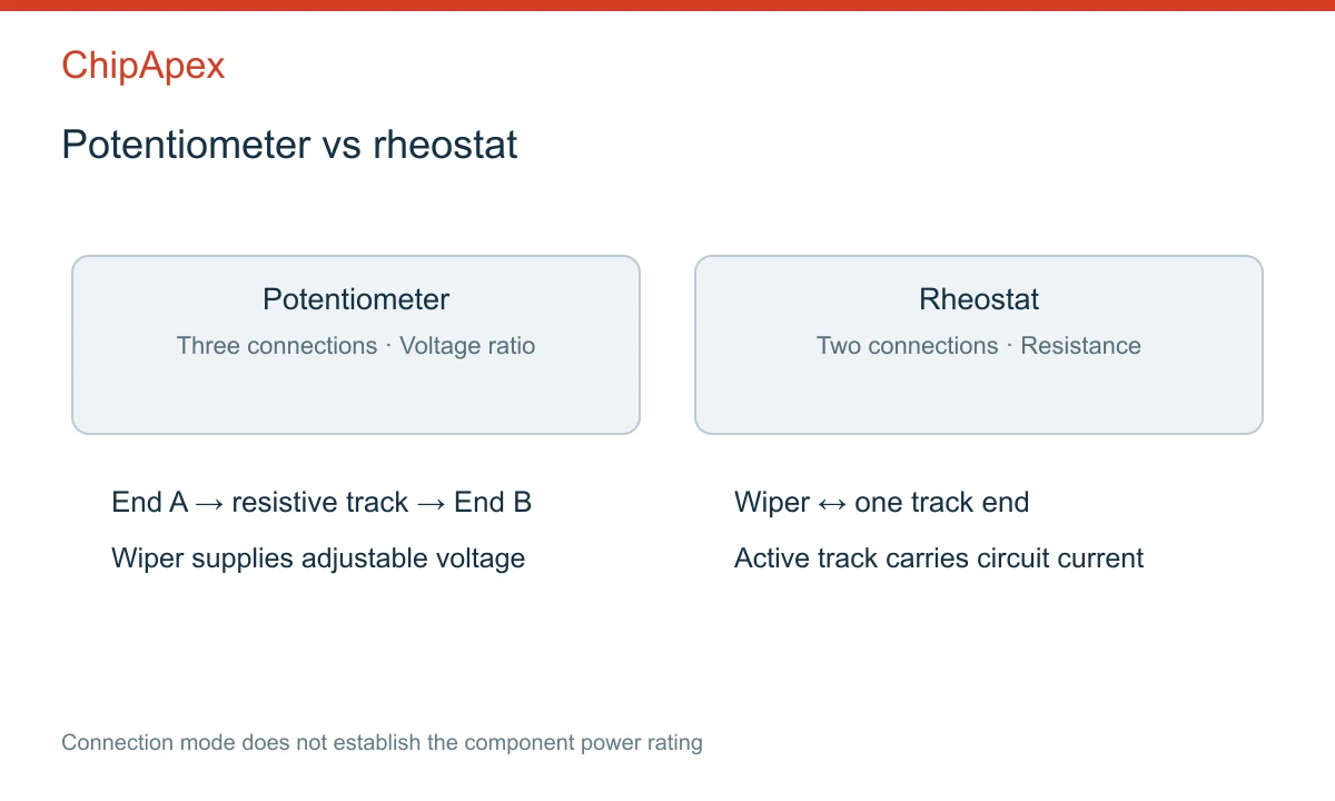
Some dedicated rheostats are built for higher power, but construction and ratings decide this. Rotary, slider and wirewound describe other aspects of the component; they do not replace the electrical specification.
For an ideal divider, Vout = Vin × Rlower / (Rupper + Rlower), where Rlower is the resistance from the wiper to the lower-potential track end. This expression assumes that the load does not significantly draw current from the wiper.
For example, a 10 kΩ linear potentiometer connected across 5 V produces approximately 2.5 V at its electrical midpoint when unloaded. The track current is 0.5 mA and total track dissipation is 2.5 mW. Real values depend on tolerance, taper, contact resistance and end resistance.
Now connect a 10 kΩ load from the midpoint wiper to the lower end. The lower 5 kΩ section is in parallel with the load, giving about 3.33 kΩ. The output becomes approximately 2.0 V rather than 2.5 V. This idealized example shows why the receiving circuit's input impedance matters.
A buffer can reduce loading where appropriate. An instrumentation op amp is relevant to some differential measurement arrangements, but a simpler buffer may be sufficient for a basic divider. Select the amplifier architecture from the actual input and output requirements.
Using the wiper and one end creates a variable resistor. In some circuits, the unused end is connected to the wiper so that loss of wiper contact leaves a defined full-track path rather than an open circuit. Whether that behavior is acceptable depends on the circuit's failure requirements.
That connection is not a universal safety measure. Full resistance may still be an unsafe state in a particular feedback or control circuit. Analyze open contacts, broken tracks and short circuits instead of assuming one wiring trick makes the design fail-safe.
The wiper has a current limit, and the active portion of the track has a dissipation limit. Near one end, only a small part of the track may carry the adjustment current. Applying the full component wattage to that small section can overheat it.
For a uniform track under an applicable manufacturer derating model, a useful screening relationship is that allowable active-section power decreases with the fraction of resistance in use. The exact rule and wiper limits must come from the selected part. Do not assume the full-track power rating remains available at every setting.
Linear taper gives an approximately proportional resistance change with position. Logarithmic or audio taper gives a different relationship suited to some level controls. Taper lettering is not universally consistent across manufacturers, so read the curve rather than relying only on a letter printed on the case.
Wirewound parts can have discrete resistance steps as the wiper moves between turns. Other track materials have different noise, wear and stability characteristics. Multi-turn adjustment can improve setting precision but does not automatically improve resistance tolerance or long-term drift.
A trim potentiometer is commonly intended for calibration or infrequent adjustment. A panel control may be designed for repeated user operation. Check rotational life, torque, shaft dimensions, mounting and environmental sealing for the actual use.
A digital potentiometer uses an electronically selected resistance network or wiper position. It can provide repeatable software-controlled adjustment, but its terminals usually have strict voltage and current limits relative to its supplies.
It is not a drop-in replacement for a high-power rheostat. Resolution, wiper resistance, terminal range, startup setting and nonvolatile memory behavior can all matter. Verify whether the device supports the intended divider or rheostat configuration.
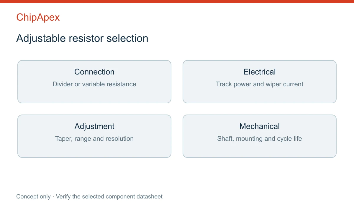
For an ADC setpoint input, consider the converter's input loading and acquisition behavior. A high-resistance divider may require a buffer or more settling time. For a feedback adjustment, verify loop stability and the effect of wiper faults across the full adjustment range.
Send ChipApex the nominal resistance, taper, power rating, intended connection mode, wiper current, mechanical drawing and quantity. Include adjustment frequency and the required failure behavior where relevant.
The potentiometer handbook provides detailed background on construction and application considerations. Use the exact product datasheet for approval, particularly when replacing a part in an existing control or power circuit.
Many can be connected that way, but the wiper current, active-track power, voltage and mechanical requirements must remain within the part's limits.
It changes resistance. The resulting current and voltage changes depend on the rest of the circuit and the load.
The load changes the effective resistance of the divider. Use the loaded-divider calculation and check whether buffering is needed.
It often is on familiar packages, but not universally. Use the terminal drawing or a suitable unpowered resistance check to identify it.
Usually it is better used as a low-power command input to a suitable controller. Direct series control requires a component rated for the actual current and heat over the full adjustment range.
Choose a DIP switch by contact type, coded positions, footprint and signal ratings. Check logic polarity, assembly conditions and PCB configuration behavior.
View details
A positive temperature coefficient (PTC) thermistor is a resistor whose resistance rises as its temperature rises. Depending on its material and curve, that change can be gradual or very steep around a transition temperature. Designers use PTC par...
View details
Learn what an integrated circuit is, how ICs work, the main types and the specs to check before choosing a part for your design with ChipApex.
View details
Understand UART protocol framing, baud rate and electrical interfaces. Learn 8N1 timing, TX/RX wiring, buffering and practical troubleshooting steps.
View details
The activity of extra discounts on wholesale prices is in full swing…
Please fill in your contact information and we will send you the latest wholesale price list.

