 ChipApex | Global Electronic Components Supplier

SEARCH
Search Product
Search Post
— IC芯片 | 连接器 | 传感器 | 被动器件 —
Search productSearch post
— IC芯片 | 连接器 | 传感器 | 被动器件 —
The trend of science and technology is changing rapidly.
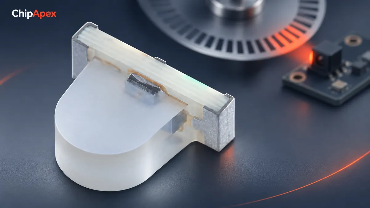
A phototransistor is a light-sensitive transistor that converts incident light into a change in collector current. Internal transistor gain amplifies the light-generated signal, allowing relatively simple detection circuits. Its useful sensitivity and speed depend on wavelength, illumination, bias, load resistance and whether the device operates in its active region or saturation.
In a common bipolar phototransistor, light reaches a photosensitive junction and generates carriers. Transistor action increases the resulting collector current. Many devices expose only collector and emitter connections; others provide a base connection that permits additional control of gain or leakage behavior.
Light changes current rather than providing a ready-made logic level. A load resistor or another signal-conditioning circuit converts that current into voltage. The following circuitry interprets the voltage as an analog value or a switching state.
The Phototransistors category includes detector components with different packages and optical characteristics. A clear lens, a dark filter and a side-looking package can have different spectral or viewing behavior. Identify the exact part rather than choosing by appearance.
| Detector | Electrical behavior | Common reason to choose it | Main tradeoff |
|---|---|---|---|
| Phototransistor | Light-controlled current with internal gain | Simple presence or interruption detection | Gain variation, speed and linearity |
| Photodiode | Photocurrent often used with an amplifier | Fast or controlled analog measurement | Amplifier and noise design may be required |
| Photoresistor | Light-dependent resistance | Slow light-level response where appropriate | Response time and material characteristics |
Internal gain can make a phototransistor convenient for a threshold circuit. It does not mean the device is universally more accurate or detects a lower signal in every measurement system. Compare the whole circuit’s noise, gain and bandwidth at the intended operating point.
An optocoupler combines an emitter and receiver in an isolation package; a discrete phototransistor does not provide isolation on its own. Check whether the requirement is free-space light detection or an electrically isolated signal path before sourcing a replacement.
For a common NPN circuit, connect the emitter to ground and the collector to the supply through a pull-up resistor, taking the output at the collector. Increasing illumination increases collector current and lowers the output voltage until the circuit reaches its limiting region. Confirm the real device pinout before connecting it.
In the active region, a simplified relationship is Vout ≈ VCC − IC × RL. With an assumed 3.3 V supply, 10 kΩ resistor and 100 µA collector current, the calculated output is about 2.3 V. This is an illustrative calculation; actual photocurrent must come from the selected device’s specified conditions or measurement.
An emitter-load arrangement gives a rising voltage with increasing current, within its compliance range. Both arrangements need checks for the receiving circuit’s input range. TT Electronics’ application note describes active and switching configurations. [1]
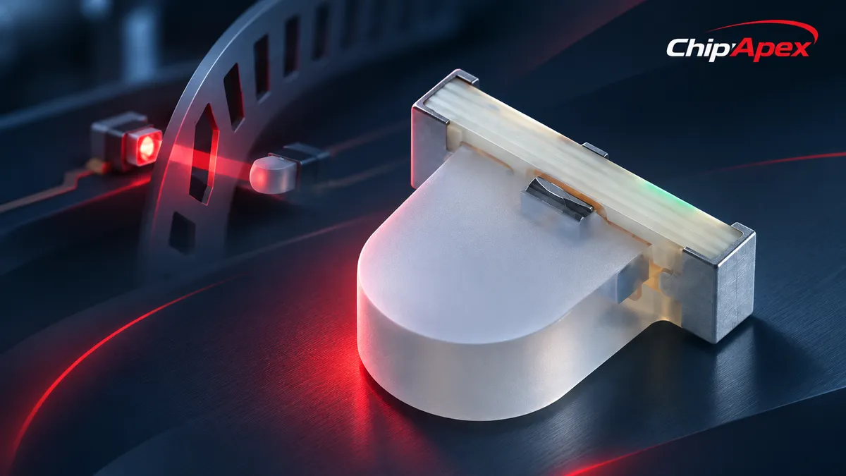
Choose the resistor using the weakest useful light signal, the strongest background signal and the required response time. A larger resistance can create a larger voltage change from a small current. It can also reduce the available current range before clipping and interact with capacitance to slow the response.
For a digital threshold, ensure the illuminated state crosses the input’s low-level threshold with margin while the dark or background condition remains above the high-level threshold. Include device variation and temperature effects. For an analog measurement, preserve headroom across the expected light range instead of driving the transistor deeply into saturation.
Vishay’s ambient-light sensor note shows that resistor choice depends on illumination and output-current variation. Its specific resistor values apply to the devices and circuit in that note; they are not universal phototransistor design values. [2]
Saturation can make a switching state easy to detect, but stored charge can delay turn-off. A detector that meets a timing requirement under one resistor and illumination condition may respond differently in a deeply saturated circuit. Use the datasheet’s test conditions when interpreting rise and fall times.
Dark current is the current that flows without the intended illumination. It generally changes with temperature. Ambient light adds another background contribution and may leave little headroom for the wanted signal. Optical shielding, wavelength selection and emitter modulation can help when supported by the system.
The sensing path also changes with alignment, distance and contamination. Test the minimum expected light current and the maximum unwanted current rather than adjusting a prototype around one convenient sample. Keep electrical and optical tolerances in the same assessment. [3]
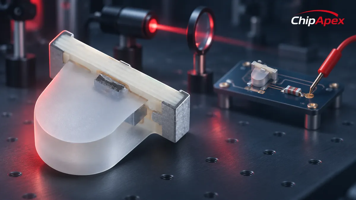
Check peak sensitivity and spectral bandwidth against the light source. Record viewing angle, package orientation and any optical filter. Then compare photocurrent at specified illumination, dark current, voltage limits and switching conditions. Photocurrent figures measured at different irradiance or wavelength are not directly comparable.
ChipApex lists XZRNI56W-1 as a side-view SMD phototransistor associated with a 940 nm sensing description. Use the exact manufacturer documentation to confirm the spectral response, mechanical orientation and electrical ratings. A catalog wavelength label alone does not establish compatibility with every infrared emitter.
For a larger detection assembly, Optical Sensors may provide other device types. A bare detector and a complete threshold-output sensor require different supporting electronics.
First verify supply polarity, the package pinout and the load connection. Measure the output with the intended emitter off and on, then repeat at the maximum distance and least favorable alignment. Test background light from the directions likely in service.
Use an oscilloscope for a moving or pulsed target. Observe both transitions; a correct steady-state voltage does not prove that the circuit resolves short events. If a brighter emitter makes turn-off worse, check saturation before increasing gain or resistance again.
Some devices respond over both regions, while filters and semiconductor material restrict others. Match the full spectral response to the intended source. The package’s appearance is insufficient to identify its useful wavelength range.
The base can be left without an external terminal because light provides the control signal. Two-pin parts still contain transistor action internally. Three-terminal devices allow additional base circuitry when their design supports it.
It usually needs a load or signal-conditioning circuit. Verify the output range and input thresholds, including the microcontroller’s supply state. A comparator with hysteresis may be appropriate when the optical signal crosses a threshold slowly or noisily.
No. It increases voltage response to a given current within the valid region, but it can reduce bandwidth or drive the circuit into saturation. Choose it with the light range, background current and timing requirement together.
Provide the exact part number or required wavelength, package, viewing direction, photocurrent test conditions and response time. Include the emitter and circuit conditions where possible. ChipApex inquiries can also specify quantity and acceptable mechanical alternatives without assuming electrical equivalence.

See how a MEMS gyroscope measures angular rate, why its angle estimate drifts, and which range, noise, interface and temperature specs to compare.
View details
Navigate the MPU landscape (NXP, TI, ST) with our guide. Discover ARM Cortex-A architecture, hidden costs of MPUs, longevity risks, and source authentic industrial-grade MPUs with full BOM support at ChipApex.
View details
Choose a vibration sensor for machine monitoring. Compare sensing methods, bandwidth, noise and mounting, then define the signal-chain requirements.
View details
Choose an AC to DC converter by input range, output demand, isolation, efficiency and thermal derating. Compare architectures and check installation needs.
View details
The activity of extra discounts on wholesale prices is in full swing…
Please fill in your contact information and we will send you the latest wholesale price list.

