ChipApex | Global Electronic Components Supplier
SEARCH
Search Product
Search Post
— IC芯片 | 连接器 | 传感器 | 被动器件 —
Search productSearch post
— IC芯片 | 连接器 | 传感器 | 被动器件 —
Consult the customer manager about the wholesale price.
consultation hotline:86-132-6715-2157
email:[email protected]
Contact the product manager for consultation. One-stop consultation is available.
Do you want a lower wholesale price? Please send us your inquiry and we will reply immediately.
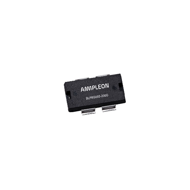
The BLP05H6700XRG is a 700 W extra rugged LDMOS power transistor designed for HF to 600 MHz applications. It operates at 50 V with a drain-source breakdown voltage of 135 V and a gate-source threshold voltage ranging from 1.33 V to 2.33 V. The device delivers a typical power gain of 26 dB and drain efficiency of 75% at 108 MHz pulsed RF operation. Thermal resistance from junction to case is 0.21 K/W, supporting high-power density. It features integrated dual-sided ESD protection and withstands VSWR up to 65:1.
Verify the specific package variant required for the design. The BLP05H6700XRG utilizes the SOT1204-3 plastic heatsink small outline package with gull wing leads. Confirm that the ordering suffix matches the intended lead form factor, as the XR variant uses flat leads in the SOT1138-3 package. Ensure compliance with RoHS requirements by checking the manufacturer's product details page before finalizing procurement specifications.
Select this component for designs requiring high power output in the HF to 600 MHz range. The 50 V operating voltage simplifies broadband impedance matching networks compared to higher voltage alternatives. Consider the thermal management requirements based on the 0.21 K/W junction-to-case thermal resistance. Verify that the application environment accommodates the specified maximum junction temperature of 225 °C and case temperature limits.
This part belongs to the BLP05H6700XR/H6700XRG family of power LDMOS transistors manufactured by Ampleon. The XRG suffix specifically denotes the SOT1204-3 package configuration featuring gull wing leads, distinct from the XR variant which uses straight leads in the SOT1138-3 package. Both variants share identical electrical characteristics and are optimized for broadcast and industrial RF power amplification.
The BLP05H6700XR serves as the functional equivalent within the same family but utilizes a different package (SOT1138-3 with flat leads). Direct substitution requires verifying PCB footprint compatibility due to the difference between gull wing and straight lead configurations.
 BLP05H6700XRGY
The activity of extra discounts on wholesale prices is in full swing…
Please fill in your contact information and we will send you the latest wholesale price list.