 ChipApex | Global Electronic Components Supplier

SEARCH
Search Product
Search Post
— IC芯片 | 连接器 | 传感器 | 被动器件 —
Search productSearch post
— IC芯片 | 连接器 | 传感器 | 被动器件 —
Consult the customer manager about the wholesale price.
consultation hotline:86-132-6715-2157
email:[email protected]
Contact the product manager for consultation. One-stop consultation is available.
Do you want a lower wholesale price? Please send us your inquiry and we will reply immediately.
CDCF2510PW is listed in the Application Specific Clock/Timing range at ChipApex. The manufacturer field lists Texas Instruments. Its product description is IC 3.3V PLL CLOCK-DRVR 24-TSSOP. Review the specifications below when checking this part for your BOM.
The CDCF2510PW is a 3.3-V phase-lock loop (PLL) clock driver designed for synchronous DRAM applications, specifically meeting PC133 SDRAM registered DIMM specifications. It distributes one clock input to ten outputs with low skew and low jitter characteristics. The device operates within a frequency range of 25 MHz to 140 MHz and includes integrated series damping resistors to eliminate the need for external RC networks. It features an output enable pin to control all ten outputs simultaneously.
Verify component authenticity through authorized distributors or direct manufacturer channels. Confirm RoHS compliance status and check for lifetime-buy availability as the device may be discontinued. Ensure proper handling procedures are followed due to moisture sensitivity classification.
Select this component when designing systems requiring low-jitter clock distribution for synchronous memory interfaces. Ensure the operating temperature range of 0°C to 85°C meets environmental requirements. Verify that the 3.3-V supply voltage aligns with system power rails and that the TSSOP-24 package fits the PCB layout constraints.
This device belongs to the CDCF2510 family of clock drivers from Texas Instruments. It is part of a series designed for high-speed memory applications, offering specific performance metrics for jitter and skew compared to other members in the broader clock distribution product line.
The CDCVF2510A is documented as a replacement for this device. Verify functional compatibility and pinout correspondence before substitution.
The PLL requires a stabilization time of up to 1 ms after power-up or changes to reference signals to achieve phase lock between the feedback signal and the reference signal.
AVCC provides the analog power supply reference. Strapping AVCC to ground bypasses the PLL, allowing the CLK input to be buffered directly to the outputs for test purposes.
All ten outputs are enabled or disabled via the G input. When G is high, outputs switch in phase with CLK; when G is low, outputs are disabled to a logic-low state.
Explore related parts through Clock/Timing, Integrated Circuits (ICs), all product categories, ChipApex homepage.
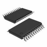 CDCF2510PW
CDCF2510PW is listed in the Application Specific Clock/Timing range at ChipApex. The manufacturer field lists Texas Instruments. Its product description is IC 3.3V PLL…
Read More
CDCF2510PW is listed in the Application Specific Clock/Timing range at ChipApex. The manufacturer field lists Texas Instruments. Its product description is IC 3.3V PLL…
Read More
CDCF2510PW is listed in the Application Specific Clock/Timing range at ChipApex. The manufacturer field lists Texas Instruments. Its product description is IC 3.3V PLL…
Read More
CDCF2510PW is listed in the Application Specific Clock/Timing range at ChipApex. The manufacturer field lists Texas Instruments. Its product description is IC 3.3V PLL…
Read More
CDCF2510PW is listed in the Application Specific Clock/Timing range at ChipApex. The manufacturer field lists Texas Instruments. Its product description is IC 3.3V PLL…
Read More
CDCF2510PW is listed in the Application Specific Clock/Timing range at ChipApex. The manufacturer field lists Texas Instruments. Its product description is IC 3.3V PLL…
Read More
CDCF2510PW is listed in the Application Specific Clock/Timing range at ChipApex. The manufacturer field lists Texas Instruments. Its product description is IC 3.3V PLL…
Read More
CDCF2510PW is listed in the Application Specific Clock/Timing range at ChipApex. The manufacturer field lists Texas Instruments. Its product description is IC 3.3V PLL…
Read More
CDCF2510PW is listed in the Application Specific Clock/Timing range at ChipApex. The manufacturer field lists Texas Instruments. Its product description is IC 3.3V PLL…
Read More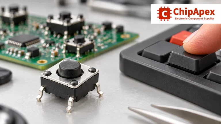
Choose tactile switches by operating force, travel, actuator height, footprint and lifetime. Check debounce, sealing and the assembled button mechanism.
Read More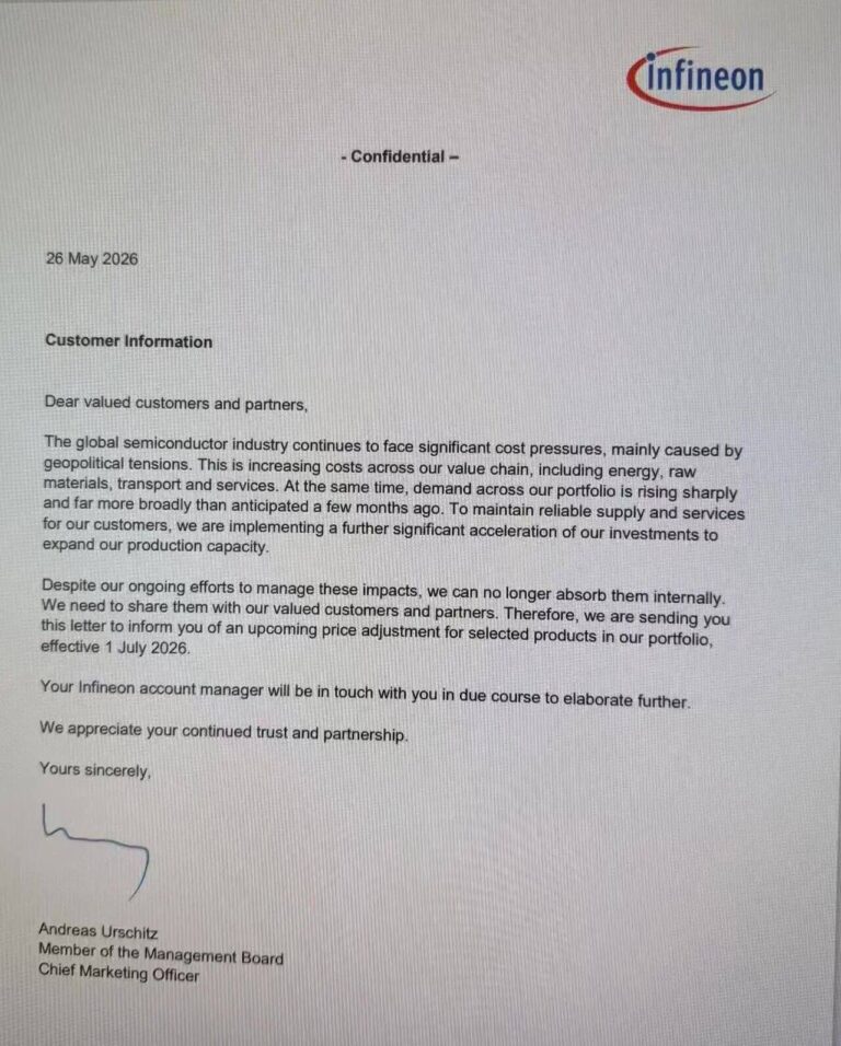
CDCF2510PW is listed in the Application Specific Clock/Timing range at ChipApex. The manufacturer field lists Texas Instruments. Its product description is IC 3.3V PLL…
Read More
CDCF2510PW is listed in the Application Specific Clock/Timing range at ChipApex. The manufacturer field lists Texas Instruments. Its product description is IC 3.3V PLL…
Read More
The activity of extra discounts on wholesale prices is in full swing…
Please fill in your contact information and we will send you the latest wholesale price list.





